FEC AFC1100 User Manual
Page 7
)(& ,QF
4.5
Wiring Diagrams
WARNING:
Follow Lockout/Tagout and other safety precautions when connecting and/or
disconnecting cabling, wiring, and equipment.
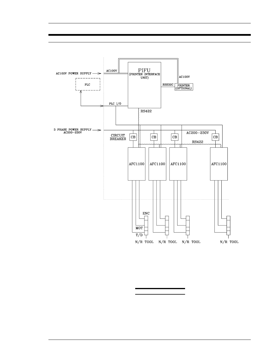
FIG. 4-5 Wiring Diagram
A basic layout of System component interconnection is shown in Figure 4-5. Detailed
reference drawings can be found throughout this Chapter, and also in Appendix A.
The layout includes a Programmable Logic Controller (PLC) and a Printer Interface Unit
(PIFU), which are not automatically supplied with the System. If a PLC is not already
available at the System installation site, one can be supplied with the System as an option.
Chapter 4: System Setup and Wiring (Rev. 8/98)
Page 4-7
See also other documents in the category FEC Accessories for electrical:
- AFC1500 (4 pages)
- AFC1500 (14 pages)
- AFC1500 (20 pages)
- AFC1500 (2 pages)
- AFC1500 (63 pages)
- AFC1500 (83 pages)
- AFC1500 (129 pages)
- AFC1500 (198 pages)
- AFC1200 (6 pages)
- AFC1200 (8 pages)
- AFC1200 (12 pages)
- AFC1200 (5 pages)
- AFC1200 (22 pages)
- AFC1200 (34 pages)
- AFC1200 (16 pages)
- AFC1200 (9 pages)
- AFC1200 (13 pages)
- AFC1200 (4 pages)
- AFC1200 (23 pages)
- AFC1200 (42 pages)
- AFC1200 (10 pages)
- AFC1200 (33 pages)
- AFC1200 (14 pages)
- AFC1200 (24 pages)
- AFC1200 (93 pages)
- AFC1200 (30 pages)
- AFC1200 (90 pages)
- AFC1150 (4 pages)
- AFC1150 (10 pages)
- AFC1150 (18 pages)
- AFC1150 (6 pages)
- AFC1100 (7 pages)
- AFC1100 (9 pages)
- AFC1100 (4 pages)
- AFC1100 (13 pages)
- AFC1100 (21 pages)
- AFC1100 (8 pages)
- AFC1100 (18 pages)
- MICRO NR (118 pages)
- FUSIONE-HS-2 (183 pages)
- DSP1500 (SAN3) (6 pages)
- DSP1500 (SAN3) (10 pages)
- DSP1500 (SAN3) (8 pages)
- DSP1500 (SAN3) (26 pages)