8 rs-422 data communication ports – FEC AFC1100 User Manual
Page 18
)(& ,QF
required spindles are functioning, and that none have been bypassed in error. The PLC can
be programmed to output a message whenever an "active" spindle has been set to IN
BYPASS, or the equipment operator can visually monitor each Axis unit.
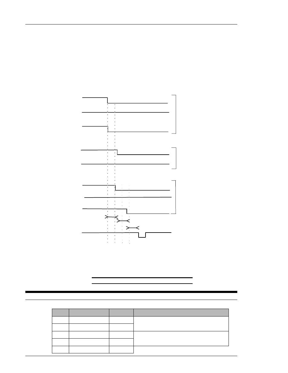
B. Fastening Work Selection and START signal input
WORK SELECT 1
WORK SELECT 2
WORK SELECT 0
BANK SELECT 1
BANK SELECT 0
BANK DATA 6
BANK DATA 7
BANK DATA 5
START
OFF
OFF
ON
50 ms
50 ms
Selection of WORK 6
BANK 1 is required for
These outputs echo WORK
(BANK 1) WORK 0
(BANK 1) WORK 1
(BANK 2) WORK 2
WORK 0~1 output display.
SELECT 0~1 inputs (pins 19,18)
when BANK 1 is active, and
OFF
OFF
(PIN 14)
(PIN 15)
(PIN 16)
(BANK DATA 5, BANK 1).
(PIN 13)
(PIN 12)
WORK SELECT 2 (pin 20) when
Reference Section 4.7.2 for
WORK 1~8 selections.
These signals will not output for
at least 50 milliseconds after the
WORK SELECT 0~2 input
signals are received.
The START signal may be input
following WORK 0~2 output.
A minimum delay of 50 millisecond
is required between the output of
WORK 0~2 signals and the
START signal input.
OFF
ON
ON
OFF
OFF
OFF
ON
ON
OFF
(BANK DATA 7, BANK 2).
BANK 2 is required for
WORK 2 output display.
BANK 2 is active.
50 ms
FIG. 4-7-7b Example of Sequence # 6 Selection
4.8 RS-422 Data communication ports.
RS-422 IN
GND
OUT
TX+
Send data to a host computer.
OUT
TX-
IN
RX-
Receive data from a host computer.
IN
RX+
DESCRIPTION
IN/OUT
SIGNAL NAME
PIN
Chapter 4: System Setup and Wiring (Rev. 8/98)
Page 4-18