FEC AFC1100 User Manual
Page 3
)(& ,QF
4.2
Component Dimensions
The specifications for all of the FEC INC. standard AFC1100 System equipment is outlined in
this Chapter to aid in determining enclosure requirements.
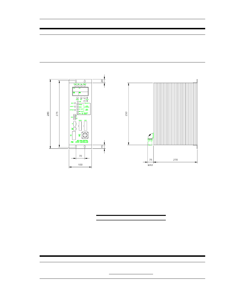
4.2.1 Axis Controller Unit Dimensions
FIG. 4-2-1 Axis Controller unit Dimensions
The Units must be mounted with a minimum clearance of 25 mm on each side to allow for
proper heat dissipation. Cable connections on the front of the Units require 100 mm of
clearance. Axis Units must be located at a minimum 300 mm from any high voltage power
source. High voltage sources such as relays, contactors, disconnects, etc. will cause
mis-operation of the AFC-1100 Axis unit. All motor cables and I/O cables must be run
separate from all high voltage sources.
4.3
Unit Arrangement
FIG. 4-3 Unit Arrangement
Chapter 4: System Setup and Wiring (Rev. 8/98)
Page 4-3
- AFC1500 (4 pages)
- AFC1500 (14 pages)
- AFC1500 (20 pages)
- AFC1500 (2 pages)
- AFC1500 (63 pages)
- AFC1500 (83 pages)
- AFC1500 (129 pages)
- AFC1500 (198 pages)
- AFC1200 (6 pages)
- AFC1200 (8 pages)
- AFC1200 (12 pages)
- AFC1200 (5 pages)
- AFC1200 (22 pages)
- AFC1200 (34 pages)
- AFC1200 (16 pages)
- AFC1200 (9 pages)
- AFC1200 (13 pages)
- AFC1200 (4 pages)
- AFC1200 (23 pages)
- AFC1200 (42 pages)
- AFC1200 (10 pages)
- AFC1200 (33 pages)
- AFC1200 (14 pages)
- AFC1200 (24 pages)
- AFC1200 (93 pages)
- AFC1200 (30 pages)
- AFC1200 (90 pages)
- AFC1150 (4 pages)
- AFC1150 (10 pages)
- AFC1150 (18 pages)
- AFC1150 (6 pages)
- AFC1100 (7 pages)
- AFC1100 (9 pages)
- AFC1100 (4 pages)
- AFC1100 (13 pages)
- AFC1100 (21 pages)
- AFC1100 (8 pages)
- AFC1100 (18 pages)
- MICRO NR (118 pages)
- FUSIONE-HS-2 (183 pages)
- DSP1500 (SAN3) (6 pages)
- DSP1500 (SAN3) (10 pages)
- DSP1500 (SAN3) (8 pages)
- DSP1500 (SAN3) (26 pages)