Teledyne 4020 – Hydrocarbon analyzer (special version for automatic background gas switching) User Manual
Page 50
Operation Model
4020
Teledyne
Analytical
Instruments
32
2. To avoid pressure shock to the instrument fuel regulator, slowly
open the secondary valve until it is wide open.
Note: adjust fuel settings only when the red LED (flame failure
light) is off.
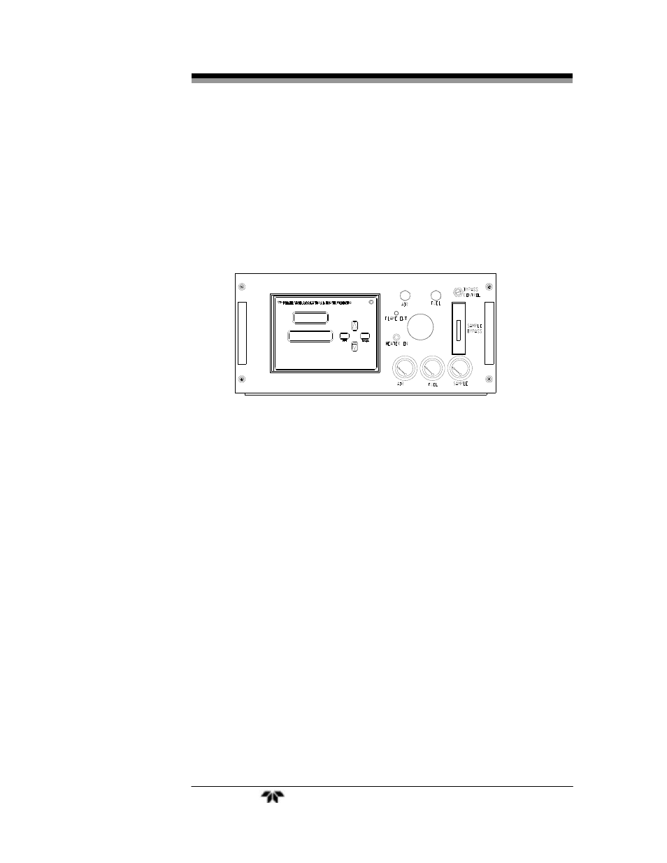
Figure 4-1: Front Panel View of Regulator and Gages
4.5 Flame Ignition
Observe that after warm up count down timer reaches zero (timer to
preheat the sensor), the amber heater lamp is blinking (indicating that
the temperature controller is maintaining the temperature setpoint) and
the red flame failure lamp is on. See Figure 4-1.
The Model 4020 will automatically attempt a flame ignition
sequence following the warm-up period which has been preset at the
factory. If the ignition process fails, the instrument will attempt to ignite
the flame a second time. If it continues to fail after the fifth attempt, a
flame failure message will appear on the display. If this occurs refer to
Section 5.
4.5.1 Verification of the Flame Guard Circuit
The operation of the flame guard circuit has been checked at the
factory, but should be re-verified during start-up. Use the following
procedure after ignition of the flame has been achieved: