4 electronics and signal processing – Teledyne 3000PB - Bulkhead mount percent oxygen analyzer User Manual
Page 23
2-7
Percent Oxygen Analyzer
Operational Theory 2
Teledyne Analytical Instruments
mizes residual gas pockets that can interfere with very low level oxygen
analysis.
The sample system for the standard instrument incorporates ¼ inch tube
fittings for sample inlet and outlet connections at the rear panel. For metric
system installations, 6 mm adapters are supplied with each instrument. The
sample or calibration gas flow through the system is monitored by a flow-
meter downstream from the cell.
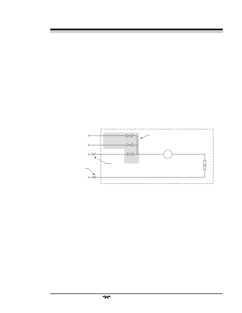
Figure 2-4 is the flow diagram for the sampling system. In the standard
instrument, calibration gases (zero and span) can be connected directly to the
Sample In port by teeing to the port with appropriate valves. The shaded
portion of the diagram shows the components added when the –C option is
ordered. The valves, when supplied, are installed inside the NEMA enclo-
sure and are regulated by the instrument's internal electronics.
Figure 2-4: Flow Diagram
2.4
Electronics and Signal Processing
The signal processing and display electronics PCBs are mounted on the
back of the inner door. See Major Internal Components in chapter 5, for
illustration. The power supply module is mounted underneath the bottom end
of the Electrical Connector Panel.
The Model 3000PB Percent Oxygen Analyzer uses an 8031 microcon-
troller with 32 kB of RAM and 128 kB of ROM to control all signal pro-
cessing, input/output, and display functions for the analyzer. System power
is supplied from a universal power supply module designed to be compatible
with most international power sources. CE approved units for the European
market also contain an EMI filter. Figure 2-5 is a simplified block diagram of
the Analyzer electronics.
In vacuum service the
restrictor should be
placed here.
Sample In
Span In
Zero In
Flowmeter
Exhaust Out
Solenoid
Valves
Restrictor
Cell
In normal service the
restrictor should be
placed here.
Components in the shaded area are in
the -C option (internal control valves)
only and are not shown in the piping
diagram above.