Teledyne 2000A-EU - General purpose thermal conductivity analyzer User Manual
Page 73
Thermal Conductivity Analyzer
Maintenance 5
5-5
Teledyne Analytical Instruments
5.6
Cell, Heater, and/or Thermistor
Replacement
The Thermal Conductivity Cell, with its Heater and Thermistor, is
mounted inside the insulated cell compartment, just behind the analyzer's
front panel access door. To remove the one of these components, you must
first slide the entire Cell Compartment out of the analyzer through the front
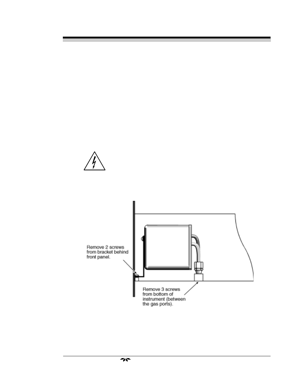
panel access door as described in the procedure below. Figure 5-5 identifies
the five screws that must be removed in order to remove the Cell Compart-
ment.
5.6.1 Removing the Cell Compartment
WARNING: IF THE MODEL 2000 ANALYZER HAS BEEN USED
WITH TOXIC GASES, FLUSH IT THOROUGHLY
BEFORE PERFORMING THIS PROCEDURE.
WARNING: DISCONNECT ALL POWER TO THE MODEL 2000
BEFORE PERFORMING THIS PROCEDURE. FAIL-
URE TO DO SO, MAY CAUSE ELECTRIC SHOCK.
Figure 5-5: Location of Cell Compartment Retaining Screws
To remove the Cell Compartment:
a. Disconnect gas and electrical connections to the analyzer.
- 1220 - Multipoint flammable gas and vapor detection system (50 pages)
- 212R - Thermal conductivity analyzer (28 pages)
- 235 - Thermal conductivity analyzer (38 pages)
- 275R - Portable turbine generator purge gas analyzer (21 pages)
- 2000XTC - Thermal conductivity analyzer (40 pages)
- 2010A - Split architecture thermal conductivity analyzer (110 pages)
- 2010B - Split architecture thermal conductivity analyzer (98 pages)
- 2020 - Explosion proof thermal conductivity analyzer (80 pages)
- 2120 - Trace Nitrogen in Argon Analyzer (66 pages)
- 2120XL - Trace Nitrogen Analyzer (85 pages)
- 2230R - Process Hydrogen Analyzer (26 pages)
- 2240 – Portable Handheld Hydrogen Leak Detector, 3rd generation (updated 1/31/11) (30 pages)
- 2240 - Portable Handheld Hydrogen Leak Detector, 3rd generation (revision 2/29/08) (40 pages)
- 2240 – Portable Handheld Hydrogen Leak Detector, 2nd generation (13 pages)
- 2750 - Portable turbine generator gas analzyer (40 pages)
- 300P - Percent oxygen analyzer (24 pages)
- 306WA - Analog trace oxygen analyzer (46 pages)
- 311 - Portable trace oxygen analyzer (19 pages)
- 311D - Portable trace oxygen analyzer with digital meter (18 pages)
- 311XL - Portable trace oxygen analyzer (18 pages)
- 316RA / RB / RAD / RBD - Oxygen analyzers (24 pages)
- 319R - Oxygen analyzer (23 pages)
- 320 Series - Portable oxygen detectors (24 pages)
- 326, 327 and 328 - Oxygen analyzers (45 pages)
- 329R - Oxygen analyzer (22 pages)
- 335 - Analog control room monitor for personnel safety (24 pages)
- 356WA - Analog trace oxygen analyzer (42 pages)
- 3000MA - Paramagnetic oxygen analyzer (63 pages)
- 3000MA - Paramagnetic oxygen analyzer Addendum (2 pages)
- 3000MB - Paramagnetic oxygen analyzer (59 pages)
- 3000PA - General purpose percent oxygen analyzer (69 pages)
- 3000PAEU - General purpose percent oxygen analyzer (78 pages)
- 3000PB - Bulkhead mount percent oxygen analyzer (82 pages)
- 3000TA - General purpose trace oxygen analyzer (75 pages)
- 3000TA-EU - General purpose trace oxygen analyzer (89 pages)
- 3000TA-XLEU - Trace oxygen analyzer (108 pages)
- 3000TB - Bulkhead mount trace oxygen analyzer (78 pages)
- 3000TB-XL - Trace oxygen analyzer (78 pages)
- 3000ZA - Trace oxygen analyzer (81 pages)
- 3000ZA-3X - Trace oxygen analyzer (72 pages)
- 3000ZA2G - Zirconium oxide analyzer (72 pages)
- 3000 Ultra Trace - PPB oxygen analyzer (72 pages)
- 3010MA - Paramagnetic oxygen analyzer, includes 0-100% range (88 pages)
- 3010MA – Paramagnetic oxygen analyzer, no 0-100% range – (superceded) (88 pages)