Installation, Install ph neutralization kit – Fulton Endura (EDR) Condensing Hydronic Boiler User Manual
Page 20
© The Fulton Companies 2014
INSTALLATION
EDR-IOM-2014-0318
SECTION 2
2-14
are not supplied with the boiler).
5. All piping (Figure 4) must be galvanized or stainless
steel, and be free of leaks. Copper, carbon steel/iron
pipe, PVC or CPVC are not acceptable.
6. Connect 1 inch (25.4 mm) condensate drain(s) (at the
rear of the boiler), to the 1 inch (25.4 mm) inlet at the
base of the drain tank. The header must be at least 5.5
inches (14.2 cm) below the condensate outlet of the
individual boiler, and must remain fl ooded - achieved
by ensuring it is at least 5.5 inches (14.2 cm) below the
outlet of the condensate drain trap.
7. Connect the 1.5 inch (38.1 mm) drain outlet to an
appropriate waste line following applicable codes. The
1.5 inch (38.1 mm) drain connection on the drain tank
must be the highest point prior to going to the drain.
Failure to keep drain piping lower than this point will
result in overfl ow of the drain tank. Slope the drain
pipe away at a minimum pitch of 1 inch (25.4 mm) for
every 12 feet (3.65 m).
8. (U.S.
Only)
Attach a ¼” water supply to the
compression fi tting on the fl oat. The water line must
be connected to an uninterruptible supply. Fulton
recommends connecting it before the “fast fi ll” valve
to the boiler supply but after the back fl ow preventer
to avoid contamination of a potable water supply.
Maximum allowable water pressure to the compression
fi tting is 100 PSI (689.5 kPa).
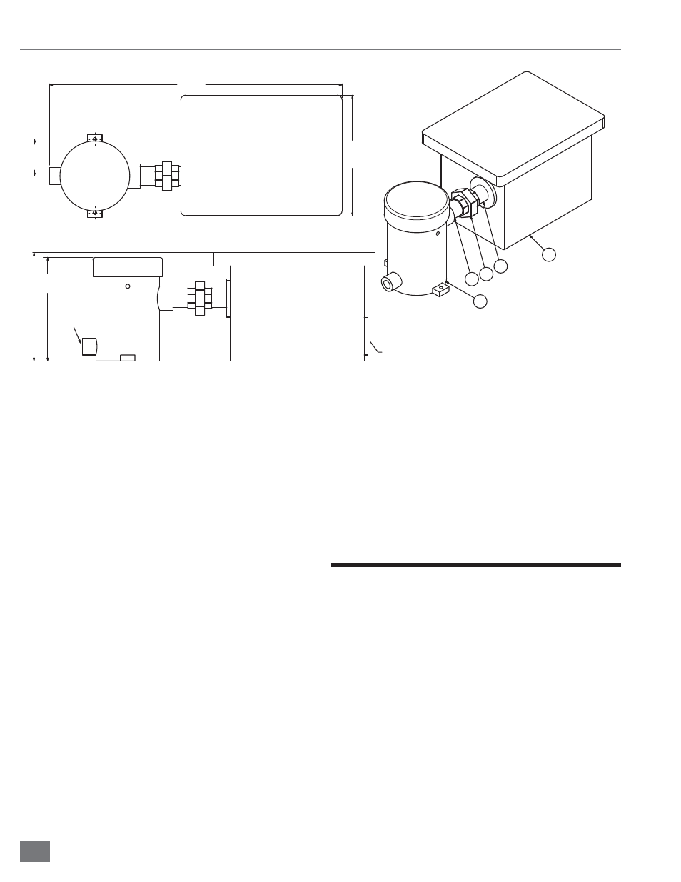
Install pH Neutralization Kit
The pH Neutralization Kit is a Fulton-provided kit designed to
bring the pH level of the boiler’s condensate to a neutral level.
It is not a replacement or alternative for the Condensate Drain
Trap. See Figure 5.
Adhere to the following for pH Kit installation:
1. Use stainless or galvanized pipe and fi ttings to connect
condensate drain to kit.
2. Connect kit downstream of Condensate Drain Trap. See
Figure 6.
3. Pipe outlet to appropriate drain.
4. Check condensate pH periodically.
TOP VIEW
30 3/8
[771]
12 1/2
[318]
3 13/16
[97]
(TYP.)
FRONT VIEW
1 1/2" PLASTIC FITTING
CONNECTION TO DRAIN
1" NPT
CONNECTION
TO BOILER
10 3/4
[273]
11 1/4
[286]
ISOMETRIC VIEW
2
3
1
4
3
1. Neutralizer Kit with Magnesium Oxide
2. Condensate Drain Kit Assembly
3. 1 1/2” by 3” NPT Stainless or Galvanized Nipple
4. 1 1/2” Stainless or Galvanized Union
FIGURE 6 - FIELD CONNECTIONS FOR CONDENSATE DRAIN TO PH NEUTRALIZATION TANK