Installation, Detail a – Fulton Endura (EDR) Condensing Hydronic Boiler User Manual
Page 18
© The Fulton Companies 2014
INSTALLATION
EDR-IOM-2014-0318
SECTION 2
2-12
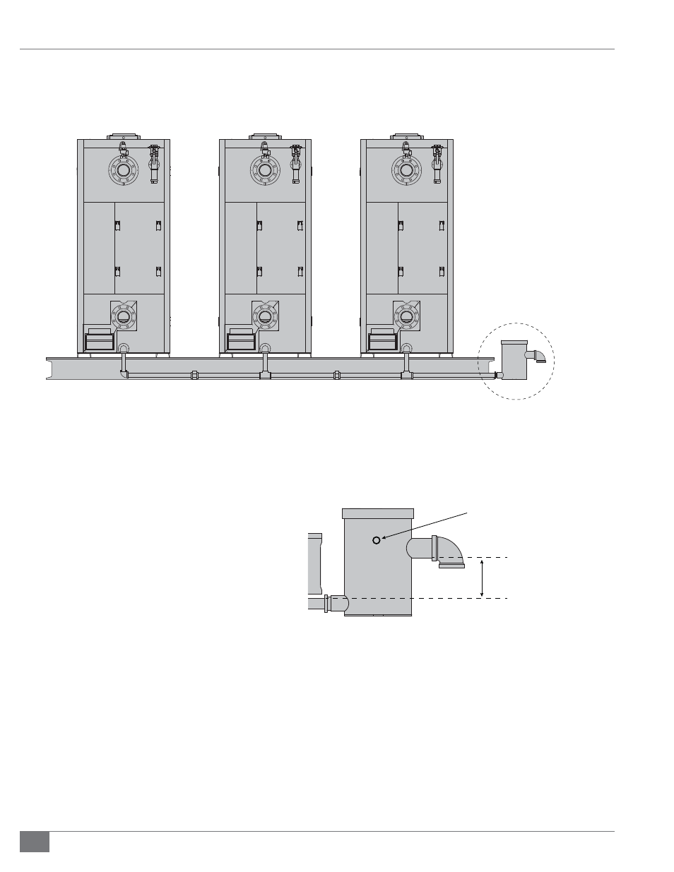
FIGURE 4 - CONDENSATE DRAIN PIPING FOR ENDURA BOILERS
Figure 4 Notes:
Header must be level or slightly pitched toward the drain.
Header material to be galvanized steel or 316L stainless.
Header should be taken to the lowest point possible and
maintain a minimum 5.5 inch (14.2 cm) drop from 1.5 inch
(38.1 mm) condensate drain kit/trap outlet. See Detail A.
1.5 inch (38.1 mm) condensate drain kit/trap outlet is never
to be above 1 inch boiler condensate outlet.
For multiple boiler installation, maintain and minimum pipe
size of 1 inch (25.4 mm) for the header piping.
The maximum capacity to attach per condensate drain kit is
12 MMBH total.
Detail A
0.25” (U.S.) TAPPING
PROVIDED FOR WATER
CONNECTION TO MAINTAIN
WATER SEAL
5.5 INCH (14.2 CM)
MINIMUM
REAR VIEW
Detail A
Condensate
Drain Kit