Experiment 1: diffraction from a single slit – PASCO OS-8523 SLIT ACCESSORY User Manual
Page 8
5
012-05880D
Slit Accessory
®
Experiment 1: Diffraction from a Single Slit
EQUIPMENT REQUIRED
– track and screen from the Basic Optics System (OS-8515)
– Diode Laser (OS-8525)
– Single Slit Disk (OS-8523)
– white paper to cover screen
– metric rule
Purpose
The purpose of this experiment is to examine the diffraction pattern formed by laser light
passing through a single slit and verify that the positions of the minima in the diffraction
pattern match the positions predicted by theory.
Theory
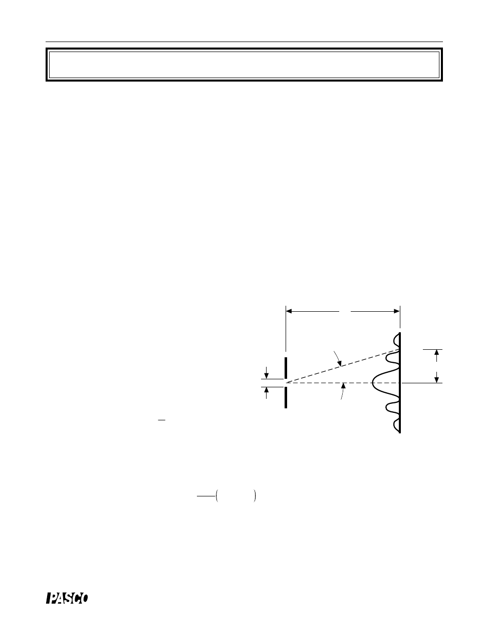
When diffraction of light occurs as it passes through a slit, the angle to the minima in the
diffraction pattern is given by
where a is the slit width,
θ
is the angle from the
center of the pattern to the m
th
minimum,
λ
is the
wavelength of the light, and m is the order (1 for
the first minimum, 2 for the second minimum, . . .
counting from the center out). See Figure 1.1.
Since the angles are usually small, it can be as-
sumed that
From trigonometry,
tan
θ
=
γ
D
where y is the distance on the screen from the
center of the pattern to the m
th
minimum and D is
the distance from the slit to the screen as shown in Figure 1.1. The diffraction equation can
thus be solved for the slit width:
a = m
λ
D
γ
m = 1,2,3,
θ
D
a
slit
screen
Figure 1.1: Single Slit Diffraction Pattern
m = 2
m = 1
m = 2
m = 1
y
a sin
θ
=
m
λ
(
m = 1,2,3...)
sin
θ ≈
tan
θ