PASCO OS-8523 SLIT ACCESSORY User Manual
Page 16
13
012-05880D
Slit Accessory
®
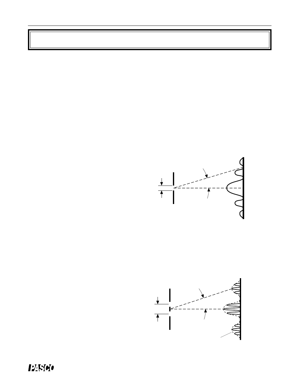
Figure 3.1: Single Slit Diffraction Pattern
a
screen
slit
EQUIPMENT REQUIRED
– track and screen from the Basic Optics System (OS-8515)
– Diode Laser (OS-8525)
– Single and Multiple Slit Disks (OS-8523)
– white paper to cover screen
Purpose
The purpose of this experiment is to compare the diffraction and interference patterns
formed by laser light passing through various combinations of slits.
Theory
When diffraction of light occurs as it passes through a slit, the angle to the minima in the
diffraction pattern is given by
a sin
θ
= m
λ
(m = 1, 2 , 3,
…
)
where a is the slit width,
θ
is the angle from the
center of the pattern to the mth minimum,
λ
is the
wavelength of the light, and m is the order (1 for
the first minimum, 2 for the second minimum, . .
. counting from the center out). See Figure 3.1.
When light passes through two slits, the two light
rays emerging from the slits interfere with each
other and produce interference fringes. The angle
to the maxima (bright fringes) in the interference
pattern is given by
d sin
θ
= m
λ
(m = 0, 1, 2 , 3,...)
where d is the slit separation,
θ
is the angle from
the center of the pattern to the mth maximum,
λ
is the wavelength of the light, and m is the or-
der (0 for the central maximum, 1 for the first
side
maximum, 2 for the second side maximum, . . .
counting from the center out). See Figure 3.2.
Setup
➀
Set up the laser at one end of the optics bench
and place the Multiple Slit Disk in its holder
about 3 cm in front of the laser. See Figure 3.3.
m = 2
m = 1
m = 2
m = 1
d
θ
diffraction envelope
slit
θ
screen
Figure 3.2: Interference Fringes
m = 0
m = 5
m = 1
m = 2
m = 3
m = 4
Experiment 3: Comparisons of Diffraction and Interference Patterns