PASCO OS-8523 SLIT ACCESSORY User Manual
Page 13
Slit Accessory
012-05880D
10
®
While the interference fringes are created by the interference of the light coming from the
two slits, there is also a diffraction effect occurring at each slit due to Single Slit diffraction.
This causes the envelope as seen in Figure 2.2.
Setup
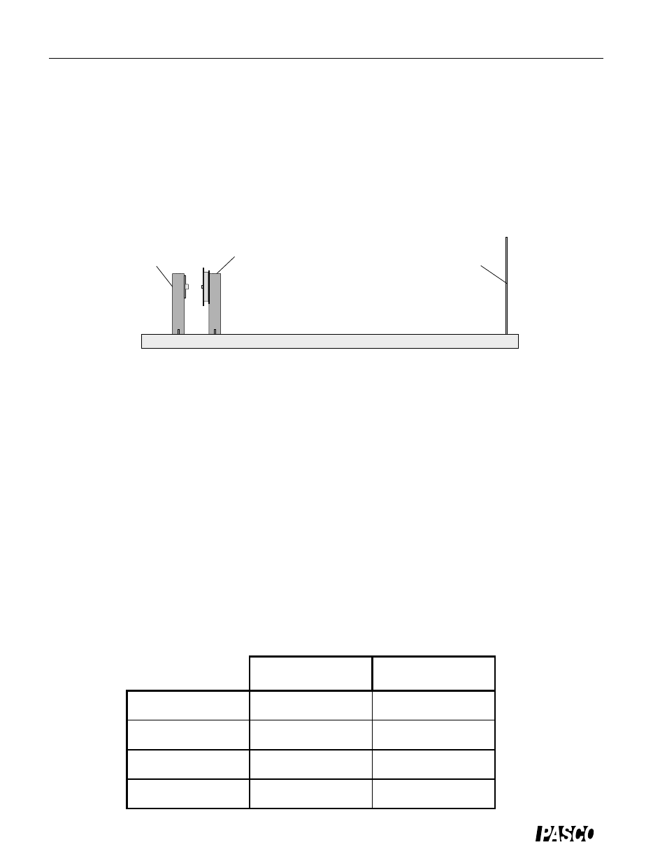
➀
Set up the laser at one end of the optics bench and place the Multiple Slit Disk in its holder
about 3 cm in front of the laser. See Figure 2.3.
➁
Cover the screen with a sheet of paper and attach it to the other end of the bench so that the
paper faces the laser.
➂
Select the double slit with 0.04 mm slit width and 0.25 mm slit separation by rotating the slit
disk until the desired double slit is centered in the slit holder. Adjust the position of the laser
beam from left-to-right and up-and-down until the beam is centered on the double slit.
Procedure
➀
Determine the distance from the slits to the screen.
Note that the slits are actually offset from the center line of the slit holder. Record the screen
position, slit position, and the difference between these (the slit-to-screen distance) in Table
2.1.
➁
Turn off the room lights and mark the positions of the maxima in the interference pattern on
the screen.
Table 2.1: Data and Results for the 0.04 mm/0.25 mm Double Slit
laser
screen
slit
Figure 2.3: Optics Bench Setup
Slit-to-screen distance (D) = _________________
First Order (m = 1)
Second Order (m = 2)
Distance between
side orders
Distance from center
to side (y)
Calculated slit
separation
% difference