Experiment 2: interference from a double slit – PASCO OS-8523 SLIT ACCESSORY User Manual
Page 12
9
012-05880D
Slit Accessory
®
EQUIPMENT REQUIRED
– track and screen from the Basic Optics System (OS-8515)
– Diode Laser (OS-8525)
– Multiple Slit Disk (OS-8523)
– white paper to cover screen
– metric rule
Purpose
The purpose of this experiment is to examine the diffraction and interference patterns formed by laser
light passing through two slits and verify that the positions of the maxima in the interference pattern
match the positions predicted by theory.
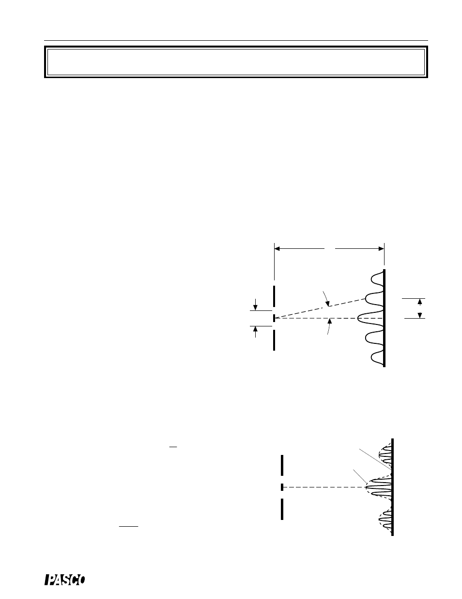
Theory
When light passes through two slits, the two light
rays emerging from the slits interfere with each
other and produce interference fringes. The angle
to the maxima (bright fringes) in the interference
pattern is given by
d sin
θ
= m
λ
(m = 0, 1, 2, 3,
…
)
where d is the slit separation,
θ
is the angle from
the center of the pattern to the m
th
maximum,
λ
is
the wavelength of the light, and m is the order (0
for the central maximum, 1 for the first side maxi-
mum, 2 for the second side maximum, . . . count-
ing from the center out). See Figure 2.1.
Since the angles are usually small, it can be as-
sumed that
sin
θ
≈
tan
θ
From trigonometry,
where y is the distance on the screen from the center of the
pattern to the m
th
maximum and D is the distance from the
slits to the screen as shown in Figure 2.1. The interference
equation can thus be solved for the slit separation:
d = m
λ
D
y
(m = 0, 1, 2, 3,
…
)
Figure 2.2: Single Slit Diffraction Envelope
Figure 2.1: Interference Fringes
D
d
screen
slit
central envelope
dotted line is diffraction envelope
m = 1
m = 0
m = 2
m = 3
m = 4
diffraction minimum
y
m = 1
m = 2
m = 2
m = 1
m = 0
θ
tan
θ
=
y
D
Experiment 2: Interference from a Double Slit