PASCO ME-8930 SMART TIMER User Manual
Page 31
012–06734A
Smart Timer
27
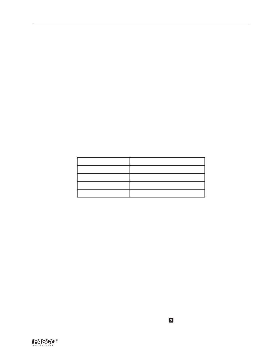
Mass of Ring
Mass of Disk
Inner Radius of Ring
Outer Radius of Ring
Radius of Disk
Table 4.1. Theoretical Rotational Inertia Data
Accounting for Friction
1. Set up the Smart Timer to measure Speed, Pulley (rev/s).
2. Tie several paper clips onto the string that hangs over the Smart Pulley.
3. Start the disk spinning slowly.
4. Adjust the hanging mass (number of paper clips) until the speed remains constant.
5. Record this “friction mass” in Table 4.2.
6. Repeat for each setup below: ring and disk combined, disk alone, and disk vertical.
Measurements for Determining the Rotational Inertia Experimentally
1. Set up the Smart Timer to measure Acceleration, Linear Pulley (cm/s
2
).
2. Find the acceleration of the ring and disk using a hanging mass of about 50 g. Wind the
thread up and let the mass fall. Record the acceleration (press
) when the mass has
fallen about 1/3 of the total fall distance (to minimize the effect of friction). Repeat at
Setup
1. Place the disk directly on the center shaft as shown in Figure 4.3. The side of the disk
that has the indentation for the ring should be up.
2. Place the ring on the disk, seating it in this indentation.
3. Mount the Smart Pulley to the base and connect it to channel 1 or 2 of the Smart Timer.
Procedure
Measurements for the Theoretical Rotational Inertia
1. Weigh the ring and disk to find their masses and record these masses in Table 4.1.
2. Measure the inside and outside diameters of the ring and calculate the radii R
1
and R
2
.
Record in Table 4.1.
3. Measure the diameter of the disk and calculate the radius R and record it in Table 4.1.