PASCO ME-8930 SMART TIMER User Manual
Page 29
012–06734A
Smart Timer
25
Experiment Four: Rotational Inertia of a Disk and Ring
EQUIPMENT REQUIRED
Rotating Platform (ME-8951)
Ohaus Triple-Beam Balance (DE-8707) or similar
Rotational Inertia Accessory (ME-8953)
paper clips (for masses < 1 g)
Smart Pulley (ME-9387)
calipers
Smart Timer (ME-8930)
Purpose
The purpose of this experiment is to find the rotational inertia of a ring and a disk
experimentally and to verify that these values correspond to the calculated theoretical values.
Theory
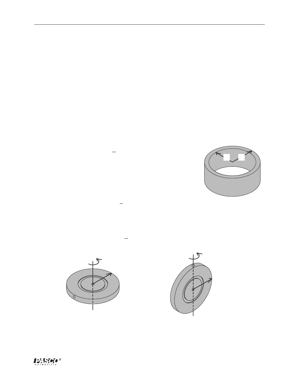
Theoretically, the rotational inertia, I, of a ring about its center of mass is given by:
where M is the mass of the ring, R
1
is the inner radius of the ring, and R
2
is the outer radius of the ring. See Figure 4.1a.
The rotational inertia of a disk about its center of mass (Figure 4.1b) is
given by:
where M is the mass of the disk and R is the radius of the disk. The
rotational inertia of a disk about its diameter (Figure 4.1c) is given by:
I = 1
2
MR
2
I = 1
4
M R
2
I = 1
2
M(R
1
2
+ R
2
2
)
Figure 4.1b
Disk rotating about its center of mass
Figure 4.1c
Disk rotating about its diameter
R
1
R
2
Figure 4.1a
Definition of R
1
and R
2
of a ring
- UI-5000 850 Universal Interface Quick Start (1 page)
- UI-5000 850 Universal Interface Instruction Manual (24 pages)
- PS-2193 High Current Sensor (2 pages)
- ME-8979 Mass and Hanger Set (1 page)
- ME-9498A Photogate Head (3 pages)
- ME-6821A Photogate Mounting Bracket (2 pages)
- ME-6825A MINI LAUNCHER (39 pages)
- ME-6810 Time of Flight Accessory (24 pages)
- ME-8574 DISCOVER FRICTION ACCESSORY (4 pages)
- PS-2103A Motion Sensor (4 pages)
- PS-2189 High Resolution Force Sensor (2 pages)
- ME-9448B Super Pulley with Clamp (2 pages)
- ME-6955 1.2 m PAScar Dynamics System (27 pages)
- PS-2104 Force Sensor (2 pages)
- ME-8998 Elastic Bumper Kit (2 pages)
- ME-6843 Spring Cart Launcher (9 pages)
- ME-6950 PAScar with Mass (29 pages)
- PS-2120A Rotary Motion Sensor (17 pages)
- PS-2120A Rotary Motion Sensor (9 pages)
- ME-9821 Centripetal Force Pendulum (18 pages)
- ME-8088 Centripetal Force Apparatus (20 pages)
- ME-8735 Large Rod Stand (2 pages)
- CI-6545 Force Accessory Bracket (3 pages)
- ME-9806 Photogate Brackets (1 page)
- CI-6692 IDS MOUNT ACCESSORY (2 pages)
- ME-6569 RMS_IDS KIT (36 pages)
- ME-6829 Mini Launcher Ballistic Pendulum (18 pages)
- ME-9889 Discover Free Fall System (10 pages)
- SE-7256 Motion Sensor Guard (2 pages)
- ME-8973 Discover Collision Bracket (2 pages)
- AP-8214A Stress_Strain Apparatus (12 pages)
- CI-6691 MINI-ROTATIONAL ACCESSORY (2 pages)
- ME-9833 Physical Pendulum Set (30 pages)
- OS-8473 POLARIZER SET (2 pages)
- PS-2343 USB Camera (2 pages)
- AP-8215A Gravitational Torsion Balance (20 pages)
- OS-8526A X-Y ADJUSTABLE DIODE LASER (2 pages)
- Xplorer-GLX Users’ Guide (152 pages)
- PS-2150 Broad Spectrum Light Sensor (2 pages)
- PS-2164 Quad Pressure Sensor (3 pages)
- PS-2200 Load Cell, 100 N (3 pages)
- PS-2205 Dual Load Cell Amplifier (5 pages)
- PS-2107 Absolute Pressure Sensor (2 pages)
- PS-2102 pH Sensor (3 pages)
- PS-2119 Acceleration Sensor (2 pages)