PASCO ME-8930 SMART TIMER User Manual
Page 15
012–06734A
Smart Timer
11
timing interval. If you wish to stop the count during a timing interval, press Start/
Stop. The display will freeze the current count and the “*” will disappear from the
first column. At this time you may select a new measurement or start a new timing
interval. The maximum counting rate for any of the counting modes is 5,000 counts
per second and the maximum count is 9,999,999.
60 Seconds: Other than timing the count interval for 60 seconds, the 60-second count
mode is the same as the 30-second mode.
5 Minutes: Other than timing the count interval for 5 minutes, the 5-minute count mode
is the same as the 30-second mode
Manual: Manual mode will count high-to-low voltage transitions on either input and
display them on the second line of the liquid crystal display. There is no time limit for
counting, however the upper limit on the number of total counts is still 9,999,999. Each
count will be accompanied by a short beep. Used with a PASCO SN-7927 G-M Tube/
Power Supply, this mode is useful for group demonstrations to show the random nature
of atomic disintegration and the inverse-square relationship between number of
disintegration’s detected and distance from the radioactive source.
Test Mode
Gates: In the Test:Gates measurement, the external measuring accessory is powered as
long as the top line of the display reads Test:Gates. This mode is useful for experiment
setup or for testing accessory photogates, G-M tubes, or other Smart Timer accessories.
Pressing the Select Measurement key will exit the test mode and remove power to the
external device. The display graphics depict a blocked photogate as a vertical line and an
unblocked photogate as an arrow.
Timing Diagrams
The timing diagrams on pages 8 and 9 show the interval, t, that is measured in each
timing mode. In each diagram, an elevated line corresponds to the photogate being
blocked, and a depressed line corresponds to the photogate being unblocked. The
calculation modes assume the use of a fence of fixed width (1 cm or 5 cm) or a pulley
having a diameter (groove to groove) of 4.8 cm and 10 spokes, such as the Super Pulley
or Smart Pulley.
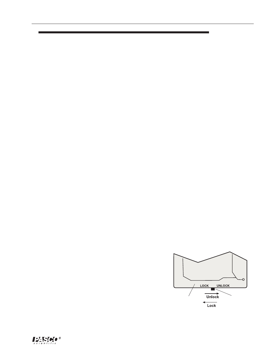
LOCK Switch
The internal LOCK switch provides a way to temporarily lock
out speed and acceleration modes. To access the LOCK
switch, turn the power off, and remove the bottom half of the
Smart Timer case as if you were going to replace the batteries.
Look along the lower edge of the printed circuit board, and
note the LOCK switch button at the edge (Figure 3). The circuit
board also has the words “LOCK” and “UNLOCK” printed
along the same edge. Moving the switch to the LOCK position
will cause the display to read MODE UNAVAILABLE
whenever speed or acceleration modes are selected.
LOCK switch
circuit board
Figure 3
Location of the LOCK switch on the circuit
board.