Set up for a diffraction pattern experiment, Introduction, Procedure – PASCO OS-8535 LINEAR TRANSLATOR User Manual
Page 9
5
012-06551A
Basic Optics Linear Translator
Set Up for a Diffraction Pattern Experiment
Introduction
The purpose is to investigate the wave nature of light. A Light Sensor measures the intensity of the interference
pattern created by monochromatic laser light passing through a single or multiple slit. The Rotary Motion Sen-
sor mounted on the Linear Translator measures the relative positions of the maxima in the pattern.
Procedure
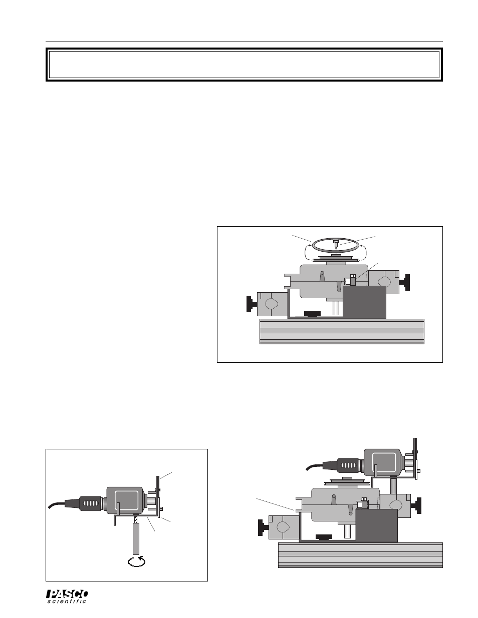
1. Put the Linear Translator onto the Op-
tics Bench so the rack is perpendicular
to the Optics Bench. Mount the Rotary
Motion Sensor onto the Rack of the
Linear Translator as described in the
Introduction. Remove the “O” ring and
thumbscrew from the Rotary Motion
Sensor pulley as shown in Figure 1 so
they will not interfere with the Aperture
Bracket.
2. Mount the Light Sensor onto the Aper-
ture Bracket by screwing the Aperture
Bracket post into the threaded hole on
the bottom of the Light Sensor as
shown.
3. Put the post into the rod clamp on the end of the Rotary Motion Sensor. Lower the Aperture Bracket until it
rests on the top of the Rotary Motion Sensor. Tighten the Rod Clamp thumbscrew to hold the Aperture Bracket
and Light Sensor in place.
EQUIPMENT NEEDED
– Optics Bench (part of OS-8515)
– Linear Translator (OS-8535)
– Aperture Bracket (OS-8534)
– Slit Accessory (OS-8523)
– Diode Laser (OS-8525)
– Rotary Motion Sensor (CI-6538)
– Light Sensor (CI-6504A)
LIGHT
SENSOR
Light
Sensor
Aperture
Bracket
post
Figure 2
screen
cable to
interface
aperture
disk
LIGHT
SENSOR
Optics Bench
Light Sensor and
Aperture Bracket
Figure 3
cable to
interface
Rotary Motion Sensor
rests on the edge of the
Linear Translator
Optics Bench
Linear Translator
Rotary Motion Sensor
rack
Figure 1
remove “O” ring
remove thumbscrew