PASCO OS-8535 LINEAR TRANSLATOR User Manual
Page 6
2
Basic Optics Linear Translator
012-06551A
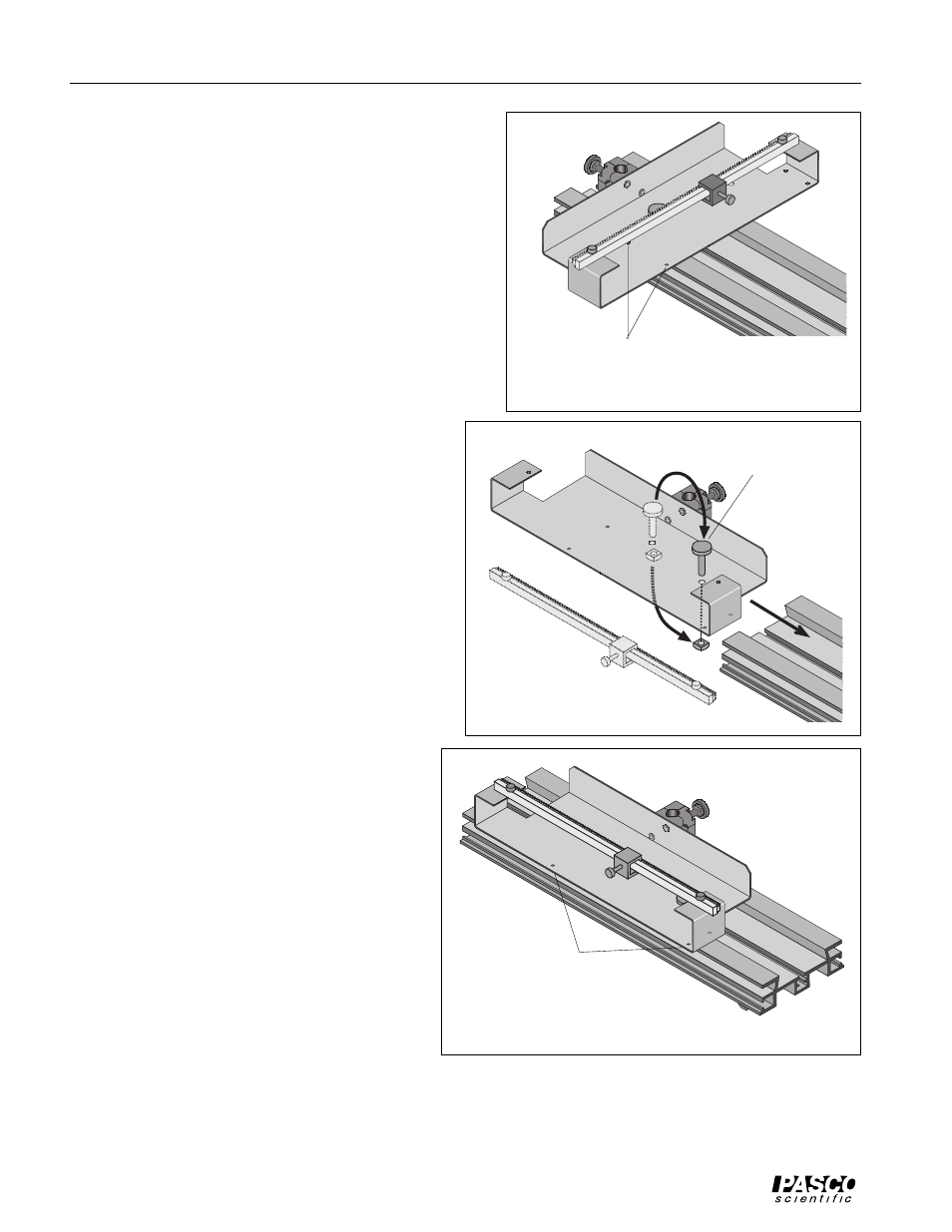
The alignment studs rest against the
edge of the Optics Bench
Figure 2: Linear Translator on Optics Bench
Pependicular Mount
To mount the Linear Translator so the Rack is perpendicular,
leave the mounting hardware (thumbscrew and square nut) in
the center hole. Loosen the thumbscrew by turning the thumb-
screw counter-clockwise while holding the square nut. Leave
the square nut on the end of the thumbscrew.
Attach the base to the Optics Bench by inserting the square nut
into the T-slot located along the center of the Optics Bench.
Use the two widely spaced alignment studs on the underside of
the base to align the Linear Translator with the edge of the Op-
tics Bench.
The Linear Translator can be moved to any position along the
Optics Bench while the thumbscrew is loose. Tighten the
thumbscrew to secure the Linear Translator in position.
Parallel Mount
To mount the Linear Translator so the Rack is parallel to
the Optics Bench, move the mounting hardware from the
center hole to the off-center hole (see Figure 3.1).
Turn the Linear Translator so the Rack is parallel to the
Optics Bench. Insert the square nut into the T-slot lo-
cated along the center of the Optics Bench.
Move the mounting hardware to
the off-center hole.
Slide the square nut
into the T-slot.
Figure 3.1
Figure 3.2: Linear Translator Parallel to Optics Bench
The alignment studs rest against
the edge of the Optics Bench.
Using a Rotary Motion Sensor
You can mount a PASCO Model CI-6538 Rotary Mo-
tion Sensor or the Model CI-6625 Rotary Motion Sensor
for ULI on the rack of the Linear Translator.
The Rotary Motion Sensor has a T-slot into which
you can slide the Rack of the Linear Translator. The
first step is to remove the rack thumbscrews from the
ends of the Rack. Turn the thumbscrews counter-
clockwise to remove them.
You may also want to remove the Rack Clamp from
the Rack. Turn the rack thumbscrew counter-clock-
wise until you can slide the Rack Clamp off the end
of the Rack.
If you are using the three-step pulley on the Rotary
Motion Sensor, hold the Rotary Motion Sensor so the
three-step pulley is on top. Line up the Rack with the
T-slot on the side of the Rotary Motion Sensor. The
teeth on the Rack go through the narrow side of the
T-slot and then engage a gear that is on the shaft of
the Rotary Motion Sensor. Gently push the Rack
through the T-Slot and into the sensor.