Data recording – PASCO OS-8535 LINEAR TRANSLATOR User Manual
Page 10
6
Basic Optics Linear Translator
012-06551A
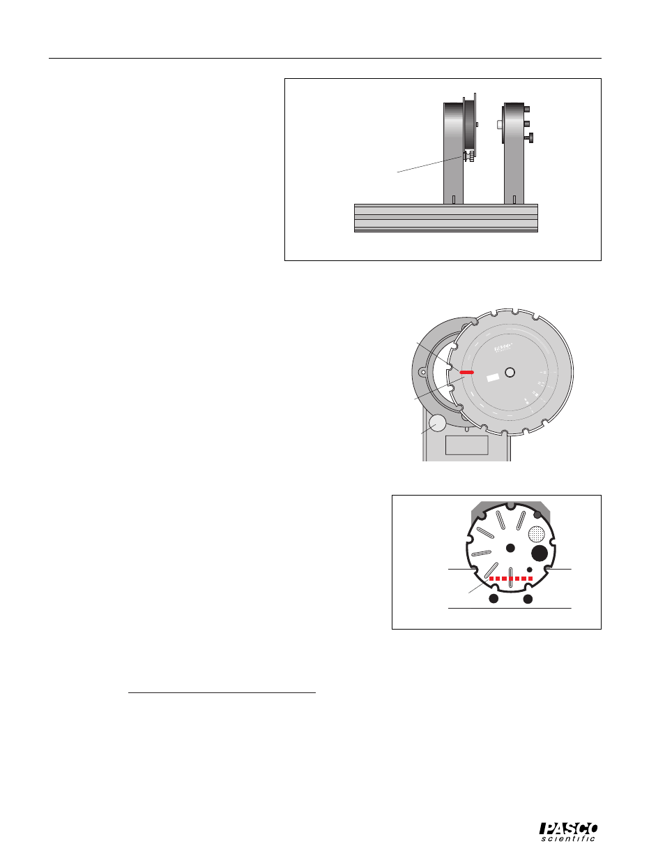
4. Mount the Diode Laser and a Slit Ac-
cessory at the other end of the Optics
Bench. For example, put the MUL-
TIPLE SLIT SET into the Slit Acces-
sory holder.
5. Plug in the power supply for the Diode
Laser. Turn on the laser.
6. Rotate the SLIT SET disk on the Slit
Accessory until a slit pattern is in line
with the laser beam. Use the adjustment
screws on the back of the Diode Laser
to adjust the beam if necessary.
7. Rotate the pulley on the top of the Ro-
tary Motion Sensor to move it along the rack on the
Linear Translator. Move the Rotary Motion/Light Sen-
sor until the white screen on the front of the Aperture
Bracket shows the diffraction pattern.
8. Examine the diffraction pattern on the white screen. If
the pattern is not horizontal, loosen the thumbscrew on
the Slit Accessory. Slowly rotate the Slit Accessory
until the laser beam is centered on the slit pattern you
want and the diffraction pattern is horizontal on the
white screen on the Aperture Bracket. Tighten the
thumbscrew on the Slit Accessory to hold it in place.
9. Rotate the Aperture Disk on the front of the Aperture
Bracket until the narrowest slit opening is in front of
the Light Sensor opening. This reduces the amount of
ambient light that can enter the Light Sensor while the Light
Sensor is between maxima of the diffraction pattern.
10. Move the Rotary Motion Sensor/Light Sensor along the rack
on the Linear Translator until the center of the difffraction
pattern is aligned with the center of the narrow slit on the
Aperture Disk of the Aperture Bracket. Loosen the Rotary
Motion Sensor rod clamp and adjust the Aperture Bracket and
Light Sensor up or down if necessary.
Data Recording
Refer to Physics Labs with Computers, Volume 2, (PASCO Model CI-7010) for information about data record-
ing using a ScienceWorkshop interface.
Slit Accessory
Diode Laser
Optics Bench
Figure 4
thumbscrew
D
O
U
B
L
E
S
L
IT
S
MU
LT
IP
LE
SL
IT
S
C
O
M
P
A
R
IS
O
N
S
VARIAB
LE
DO
UB
LE
S
L
IT
5
4
3
2
a=
0.0
4
d
=
0.
12
5
0.0
8
0.5
0
0.
08
0.
25
0
.0
4
0
.5
0
0
.0
4
0
.2
5
a
=
:
d
=
:
a =
0.0
4
d = 0.1
25
to
0.7
5
d
=
:
s
li
t
s
e
p
a
ra
ti
o
n
in
m
m
a
=
:
s
li
t
w
id
th
in
m
m
BASIC OPTICS
SLIT ACCESSOR
Y
OS-8523
MUL
TIPL
E SLIT SET
a = 0.04 0.04
d =
0.25
a = 0.04
0.04
d = 0.25
0.50
a=
0.0
4
0.08
d=
0.2
5
0.2
5
a
=
0.04
0.04
d
=
0.125
0.125
646-
0586
5
Figure 5
slit pattern
laser beam
thumbscrew
Slit Accessory
Slit Disk
diffraction pattern
white screen
Figure 6