Using the rack separately – PASCO OS-8535 LINEAR TRANSLATOR User Manual
Page 7
3
012-06551A
Basic Optics Linear Translator
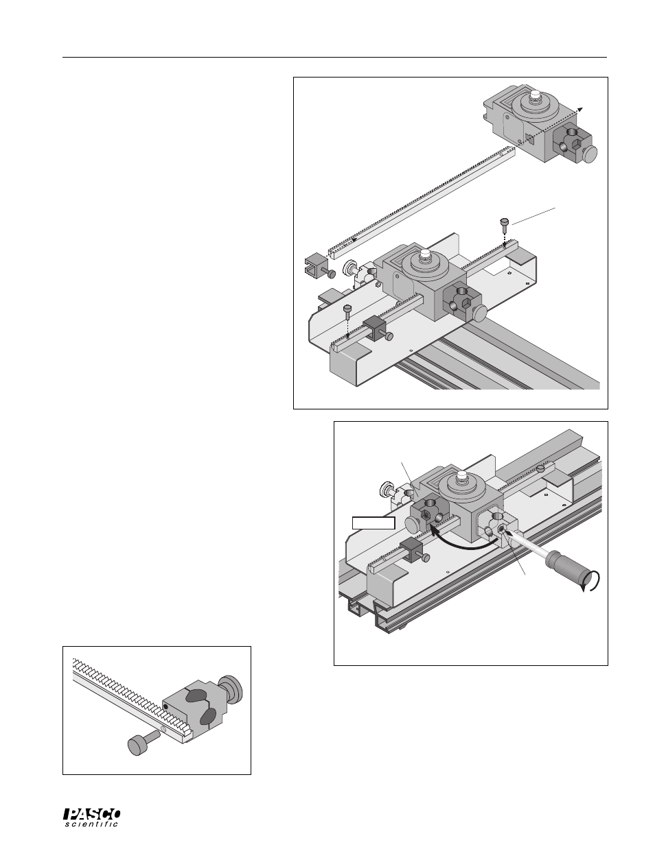
Rotary Motion Sensor
rack
rack
clamp
Linear Translator
rack thumbscrew
Figure 4.1: Rotary Motion Sensor onto Linear Translator
When the Rack is in the T-slot, put the Rack
Clamp back onto the Rack and tighten its
thumbscrew. Place the Rack with the sensor
back onto the Linear Translator. The back end
of the Rotary Motion Sensor rests on the up-
right edge of the base of the Linear Translator.
Line up the holes in the ends of the Rack with
the holes on the Linear Translator base. Put the
thumbscrews into the holes and turn them
clockwise to tighten.
If the Linear Translator is mounted parallel to
the Optics Bench, move the rod clamp from the
end of the Rotary Motion Sensor to the side of
the Rotary Motion Sensor. By doing this, the
Light Sensor will be along the center line of the
Optics Bench when you put the Aperture
Bracket post into the rod clamp of the Rotary
Motion Sensor.
You will need a Phillips head screwdriver with
a small tip (e.g., #0). Use the screwdriver to re-
move the two screws from the end of the rod
clamp. Align the rod clamp with the threaded
holes on the side of the Rotary Motion Sensor.
Replace the screws.
Using the Rack Separately
The rack of the Linear Translator can be used sepa-
rately from the Linear Translator. For example, it can
be an accessory to the Rotary Motion Sensor in experi-
ments that do not require the Optics Bench but that do
require the measurement of linear position.
Remove the two rack thumbscrews. Remove the rack
clamp from the rack. Use a Phillips head screwdriver
with a small tipe (e.g., #0) to remove the two screws
from the end of the rod clamp that is on the Linear
Translator. Use one of the rack thumbscrews to attach
the rod clamp to one end of the rack as shown. Use the
rod clamp to hold sensors, etc.
Remove the
screws from the
rod clamp.
Move the rod clamp to the side
of the Rotary Motion Sensor
and replace the screws.
Optics Bench
rod clamp
Figure 4.2: Rotary Motion Sensor on Linear Translator
Parallel to Optics Bench
rack thumbscrew
rod clamp
rack
Figure 5: Rod Clamp attached to Rack