Introduction – PASCO OS-8535 LINEAR TRANSLATOR User Manual
Page 5
1
012-06551A
Basic Optics Linear Translator
Introduction
The PASCO OS-8535 Linear Translator is designed to be mounted on the Optics Bench of the OS-8515 Basic Optics
System. The Linear Translator can also be mounted on a rod up to 0.5 inch (12 mm) diameter.
Description
The Linear Translator consists of a base with mounting hardware and an attached rod clamp, a rack, and a rack clamp.
The hole in the base allows it to be stored on a peg. The mounting hardware on the base consists of a thumbscrew and a
square nut. The nut fits into the T-slot in the center of the Optics Bench (part of the OS-8515).
The rack is attached to the top of the base with two thumbscrews. The rack is designed to fit inside the T-slot on the side
the PASCO Model CI-6538 Rotary Motion Sensor (or CI-6625 Rotary Motion Sensor for ULI). The teeth on the rack
engage a gear inside the Rotary Motion Sensor, causing the gear to rotate when the Rotary Motion Sensor moves along
the rack. The Rotary Motion Sensor measures its linear position along the rack.
The rack clamp is attached to the back of the rack with a thumbscrew. The clamp sets the initial or final position of the
Rotary Motion Sensor.
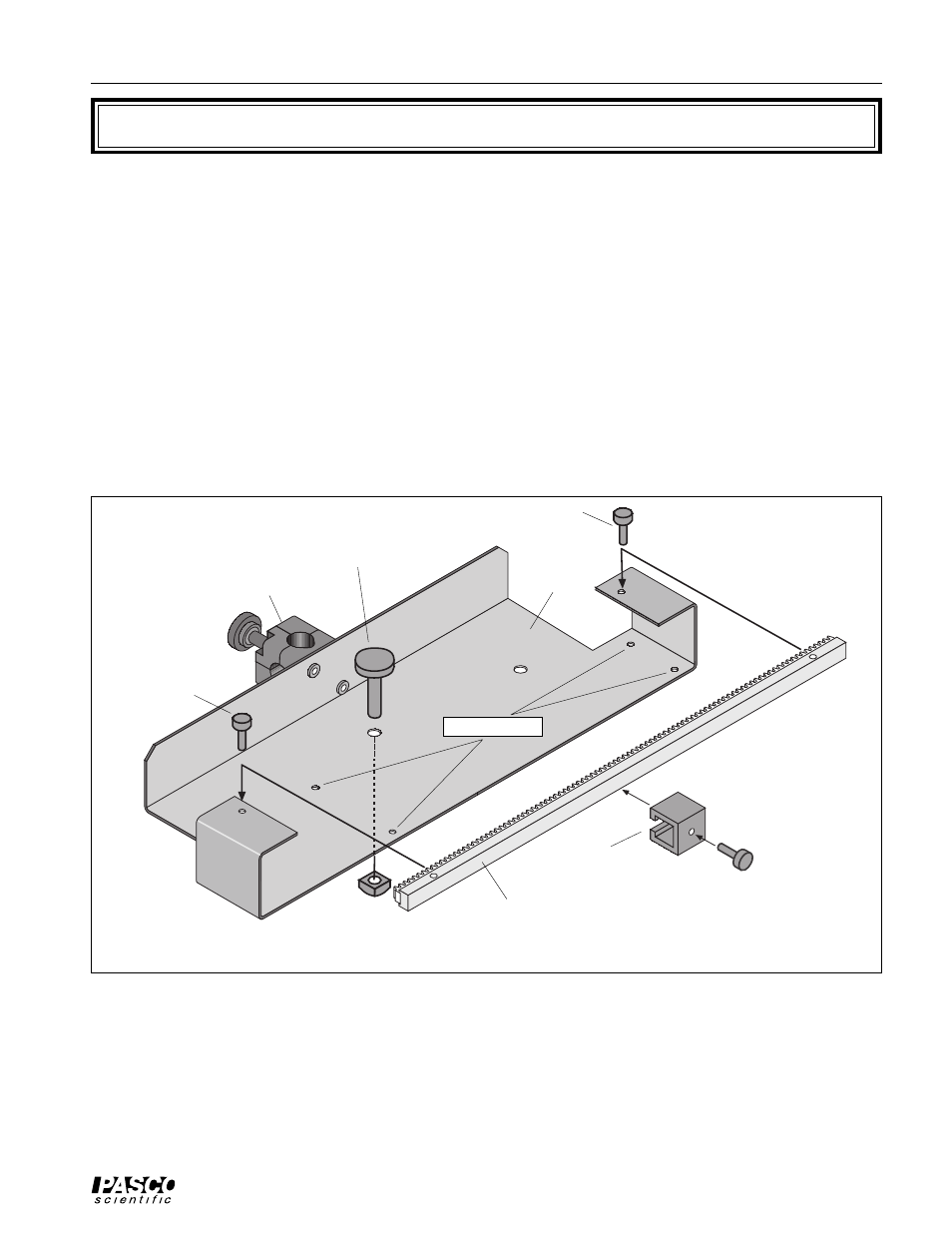
Figure 1: Linear Translator for Basic Optics
rack clamp
rack
thumbscrew
base
base thumbscrew
square nut
rod clamp
rack
rack
thumbscrew
alignment studs
Mounting the Linear Translator on the Optics Bench
You can mount the Linear Translator on the Optics Bench in two ways: with the Rack perpendicular to the Optics
Bench or with the Rack parallel to the Optics Bench.