Assembly – PASCO SE-8657 MOTOR ACCESSORY User Manual
Page 8
4
Motor Accessory
012-06247A
¨
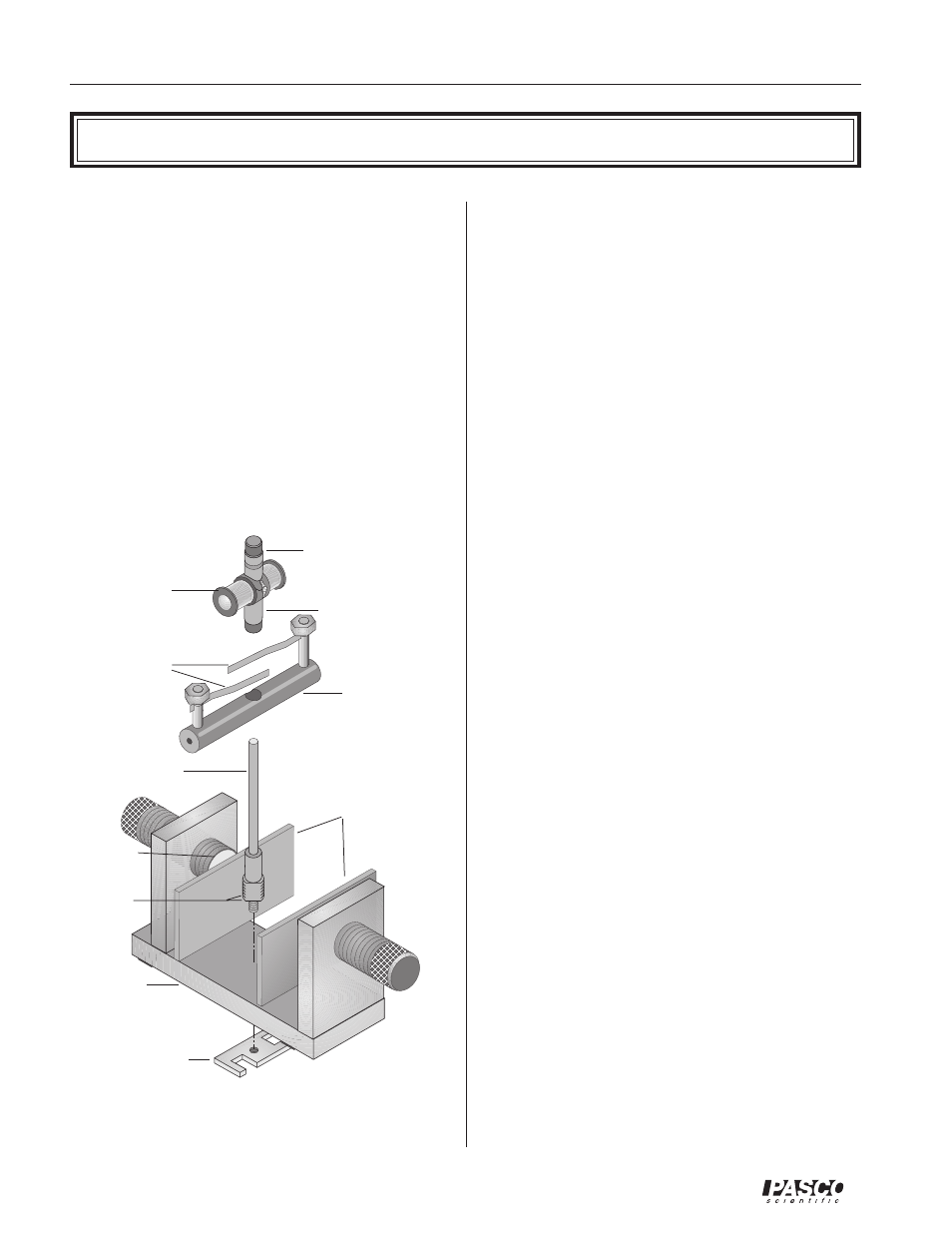
Motor Accessory onto the Variable Gap
Magnet
➀
Be sure you have the flat iron pole pieces placed on
the two neodymium magnets of the Variable Gap
Magnet. The larger threaded portion of the shaft
screws easily, without tools, into the threaded hole
in the magnet base. Insert the threaded end of the
shaft from above, screwing it in until 1 mm, or
slightly less, of the threaded portion remains above
the upper surface of the base.
➁
Turn the magnet over and screw the retaining nut
onto the smaller diameter threaded portion of the
Assembly
shaft that protrudes through the bottom of the mag-
net base. (Note that the retaining nut has a metric
thread, size M6-1.0.) Use firm finger pressure. If
this should prove inadequate, tighten the nut some-
what more with a wrench. If an appropriate wrench
is not at hand, use a heavy metal object to tighten
the nut by tapping the edge of the nut. Do not use
a pole piece of the magnet to tighten the nut be-
cause that might mar the finish of the pole piece.
Do not over tighten.
➂
Working from above, press the brush holder onto
the smooth, enlarged portion of the shaft. Apply
increasingly firm pressure equally to each side of
the brush holder while rotating the brush holder
back and forth. If this action loosens the retaining
nut, tighten it more tightly, as described in step 2.
Check to be sure the brush assembly is seated as far
down on the shaft as it will go.
➃
Gently lower the armature onto the shaft. To make
a DC motor, the split ring commutator should be
down; for an AC motor, the dual slip-ring commu-
tator should be down. Carefully rotate the arma-
ture back and forth to separate the brushes and al-
low the commutator to slip down between them. If
necessary, insert a pencil or similar object down
between the brushes. Use only the most delicate
force to avoid bending the brushes and necessitat-
ing adjustments or repairs.
➄
Adjust the gap of the Variable Gap Magnet so there
is approximately 1 mm of clearance between the
pole pieces and the armature when it is rotated by
hand.
➅
Refer to the instructions included in experiments 1-
4 for details of the electrical connections.
Motor AccessoryVariable Gap Magnet Assembly
armature
wrench/retaining
nut
brushes
brush holder
dual slip-ring commu-
tator
split ring
commutator
(this end down for
AC motor)
(this end down for
DC motor)
leave 1mm
exposed at
installation
shaft
magnet base
flat pole pieces
neody-
mium
magnet