PASCO SE-8657 MOTOR ACCESSORY User Manual
Page 31
27
012-06247A
Motor Accessory
¨
T
T
H
I
ý
G
N
L
O
M
I
R
A
N
A
D
J
U
M
A
O U
T P
A M
P L
I T
P I
- 9
5 8
7 C
D I
G I
TA
L
F U
N C
T I
O N
WA
V E
F
I
N
P
G
N
E
X
T
E
R
F R
E Q
U E
N C
Y
-
HE
RT
Z
=
D
C
400
400
wire to the coil on the opposite side of the armature, through that coil, and through the wire
to the other split ring and into the second brush. By carefully examining the part of the
coils where the leads emerge from the coil, you can determine the direction in which the
wire is wound on the coil. [Current direction is described as being from the positive to the
negative (conventional current). Note that this is opposite of the direction of electron
movement.] Draw arrows on Figure 2 showing the direction of current at various points in
the motor, armature, and wire.
➄
You can use the “right-hand rule” to predict the direction of the magnetic field of a coil.
Grasp the coil with your fingers wrapped around the coil in the direction of the current.
Your thumb will point in the direction of the field (that is, toward the north pole of the
coil). Label the ends of the coil N and S in Figure 2.
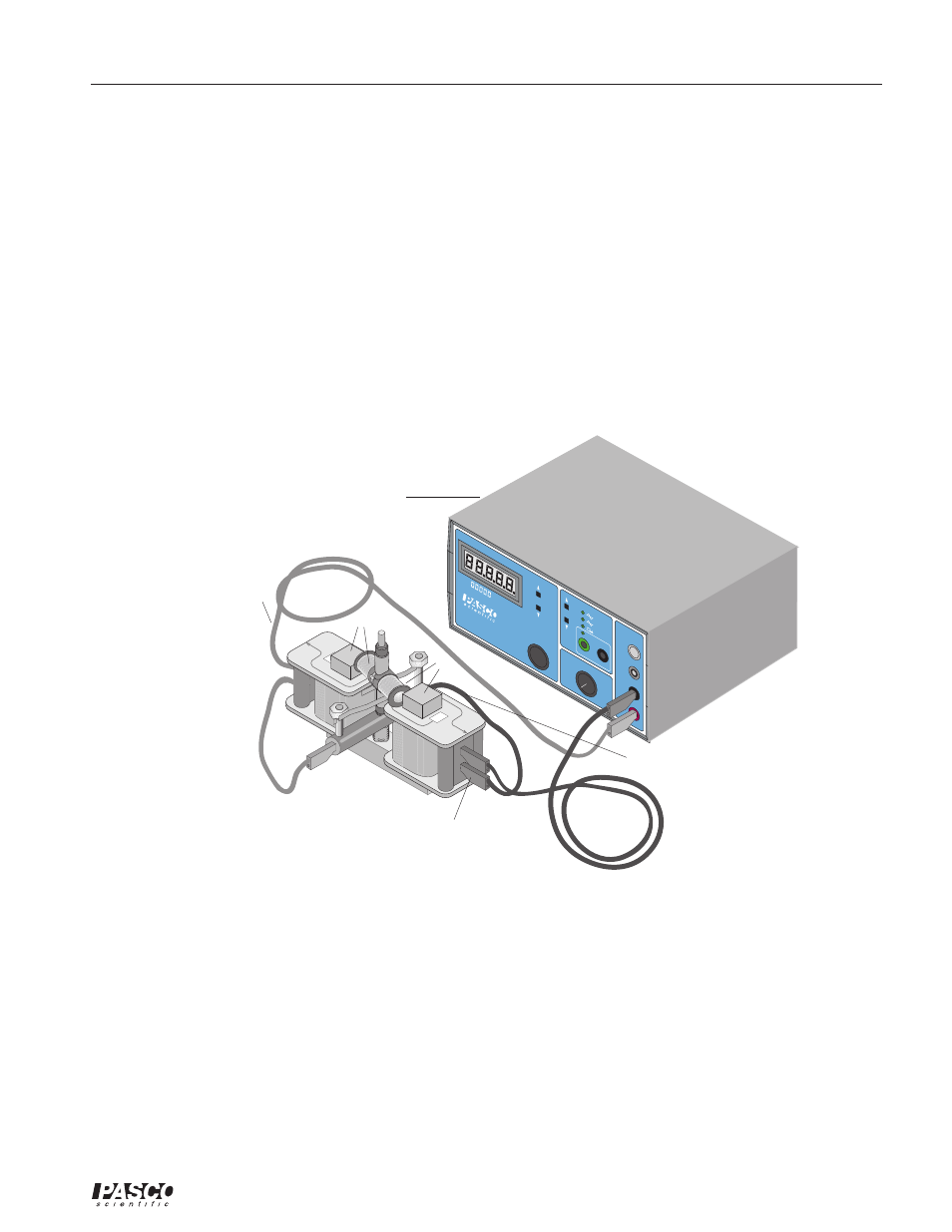
Figure 2. Experimental Setup
➅
Gently replace the armature onto the shaft. The split ring commutator should be down.
Carefully rotate the armature back and forth to separate the brushes and allow the commu-
tator to slip down between them. If necessary, insert a pencil or similar object between the
brushes to separate them. Use only the most delicate force to avoid bending the brushes
and necessitating adjustments or repairs.
➆
Use the right-hand rule to establish the location of the north and south poles of the U-
shaped core. Arrows molded into the plastic coil forms show the direction of the winding
in the coils. Label the poles on Figure 2.
Digital Function Generator-Amplifier
lead to negative brush
lead to positive
terminal or AC
lead to negative terminal or AC
N or S?
N or S?