Figure 2. experimental setup, Flat pole pieces – PASCO SE-8657 MOTOR ACCESSORY User Manual
Page 12
8
Motor Accessory
012-06247A
¨
➂
Working from above, press the brush
holder onto the smooth, enlarged portion
of the shaft. Apply increasingly firm
pressure equally to each side of the brush
holder while rotating the brush holder
back and forth. If this action loosens the
retaining nut, tighten it more tightly, as
described in step 2.
Check to be sure the brush assembly
is seated as far down on the shaft as it
will go.
➃
Gently lower the armature onto the shaft
with the split ring commutator down.
Carefully rotate the armature back and
forth to separate the brushes and allow
the commutator to slip down between
them. If necessary, insert a pencil or
similar object down between the brushes.
Use only the most delicate force to avoid
bending the brushes and necessitating
adjustments or repairs.
➄
Adjust the gap of the Variable Gap
Magnet so there is approximately 1 mm
of clearance between the flat pole pieces
and the armature when it is rotated by
hand.
➅
Connect the positive terminal of the DC
power supply to one end of the brush
holder with a red patch cord by plugging
the banana terminals into each.
➆
Connect the negative terminal of the DC
power supply to the other end of the
brush holder with a black patch cord.
Do not turn the power on.
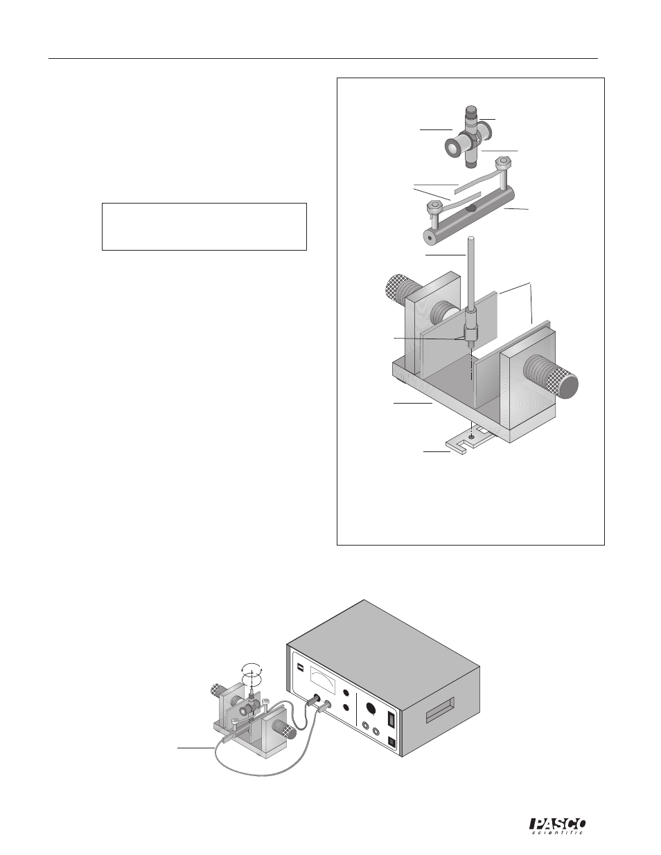
Figure 1. Installation of the Motor Accessory
onto the Variable Gap Magnet
armature
wrench/retaining
nut
brushes
brush holder
dual slip-ring commu-
tator
split ring
commutator
leave 1mm
exposed at
installation
shaft
magnet
base
Figure 2. Experimental Setup
flat pole pieces
6 AMP
MAX
RESET
ON
OFF
PASCO
scientific
METER
PUSH FOR
CURRENT
DC CURENT
ADJUST
DC VOL
TAGE
ADJUST
2
4
6
8
12
14
16
18
20
22
24
10
AC VOL
TAGE
ADJUST
2 - 24 VOL
TS
AC OUTPUT
0 - 24 VOL
TS DC OUTPUT
8 AMP
MAX
MODEL
SF-9584 LOW VOL
TAGE
AC/DC POWER SUPPL
Y
wire connected to
the + terminal of the
power supply