Electromagnetic induction, Transformers – PASCO SF-8616_8617 COILS SET User Manual
Page 6
scientific
4
012-03800A
Electromagnetic Induction
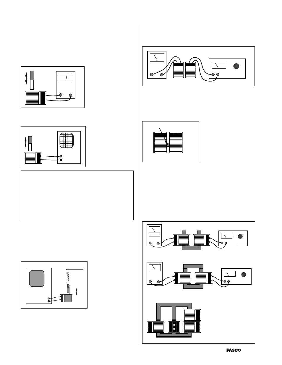
Use a small, relatively strong bar magnet to demonstrate
electromagnetic induction. It is only necessary to move the
magnet up and down in the center of the coil. If the coil is
attached to a galvanometer, the relative size of the induced
current and the direction can be noted. See Figure 11.
Galvanometer
A second way of showing the effect is to connect the coil to
an oscilloscope. See Figure 12
NOTE: A galvanometer shows the current
produced, which should be proportional to the size
of the induced voltage. Due to mechanical damp-
ing, galvanometers do not rise to the maximum
value, but give useful semi-quantitative measure-
ments of the maximum currents. An oscilloscope
shows the size of the induced voltage directly, and
gives a more instantaneous value.
The set-up below gives a method of “automatically” show-
ing the induced voltage. A light spring which gives a nice
simple harmonic motion with the attached magnet is needed.
Note that the method of attaching the magnet is via a
machine nut which is hooked to the spring and held by the
magnetic field of the magnet. See Figure 13.
TRANSFORMERS
Leading directly to the study of transformers, the setup in
Figure 14 allows students to see how induction can proceed
by passing magnetic field between the two coils. Using air
as the medium between the two coils, PASCO’s experiments
showed a drop-off to an output voltage of less than 20%
from the input voltage when the two 400-turn coils were
used in this manner.
ac power
ac volts
Figure 11
Figure 12
Figure 13
Figure 14
To improve the mutual induction, an iron core can be
introduced. See Figure 15. Using the cross piece from the
U-shaped core, the induced voltage increased to almost 50%
of the primary voltage under the same conditions as above.
Iron Core
Primary
Secondary
Figure 15
ac power
ac amperes
Without Cross Bar
ac power
ac amperes
With Cross Bar
Numerous modifications of the cores which are provided can
be investigated. In each case, the ratio of secondary voltage
to primary voltage is noted. The variables in this situation
thus become: Primary Number of Turns, Secondary Number
of Turns, Existence of a Core, Shape of the Core, Primary
Voltage, Primary Current, Secondary Voltage and Secondary
Current. Students can be led on directed studies, or given
the materials to develop their own experiments. Some
possibilities are shown in Figure 16 below.
Primary
Secondary 1
Secondary 2
Figure 16