Procedure b, Procedure c – PASCO SF-8616_8617 COILS SET User Manual
Page 16
scientific
14
012-03800A
9.
The waveform seen across the load resistance (A to C) is called a half-wave rectified signal.
Half of the full sine wave passes through the diode, with the other half being blocked. This
produces a directional current (d.c.) but one that is constantly changing in magnitude. To be
useful, the voltage level must be made constant. The addition of an electronic “damper”
should accomplish this.
Primary
A
B
C
Diode
Load
Resistor
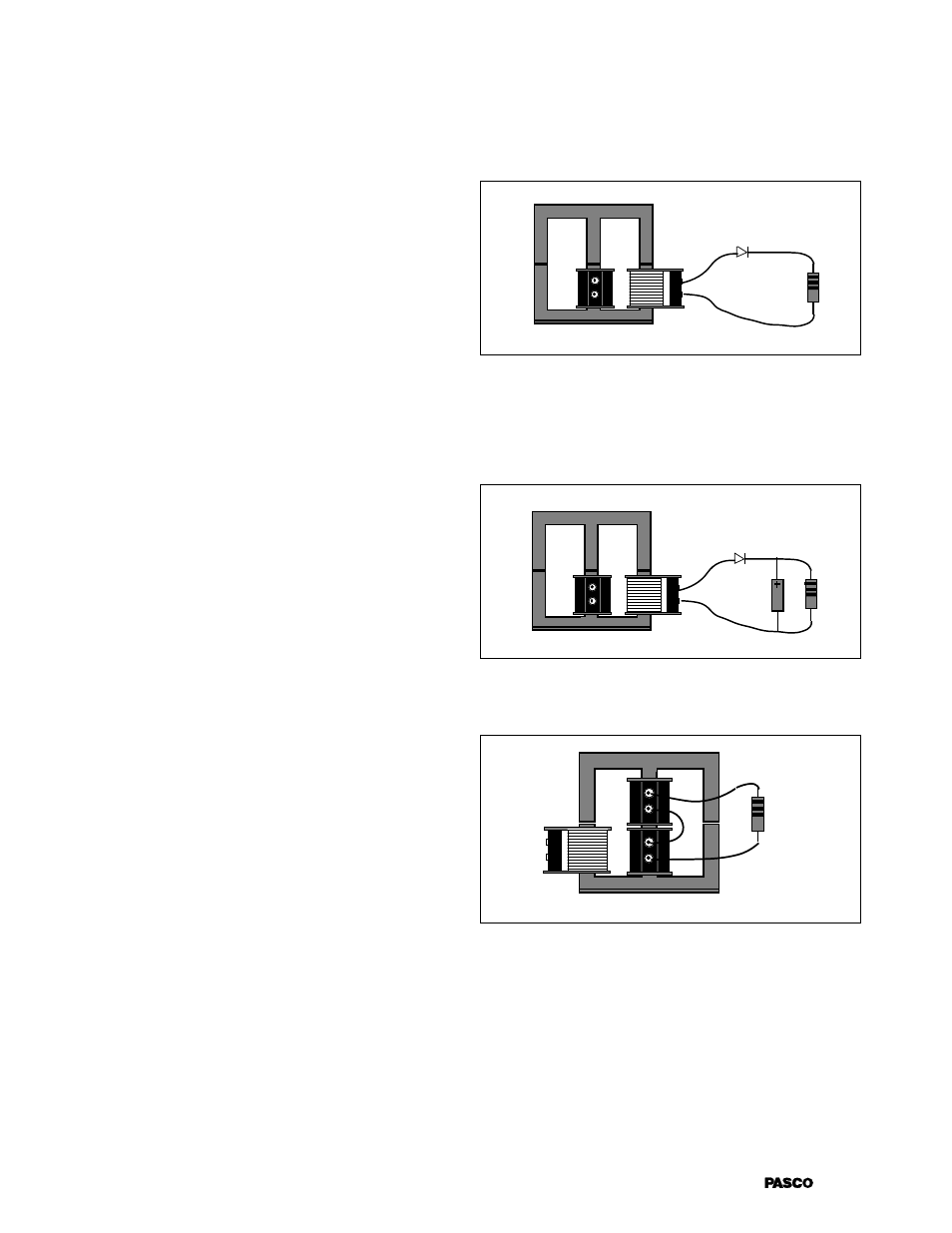
Procedure B
7.
Set up the 200-turn coil as primary, and the 800-turn coil as the secondary. Put a diode into
the circuit as shown in Figure 4, and leave the 1000-
Ω
resistor in as a load.
Figure 3
10. Add the 470
µ
F capacitor as shown in
Figure 4. What is the new waveform across
the load resistor? Is it still varying as much
as it did previously? What is the d.c. level
of the resulting voltage?
11. Now change the 1000-
Ω
resistor to a 10-
Ω
resistor in the same circuit. How does this
affect the waveform? How does it affect
the d.c. voltage?
Primary
A
B
C
Load
Resistor
•
•
Capacitor
Diode
Figure 4
Procedure C
12. Now connect the two 400-turn coils so that
they have maximum voltage and current
output. With the 1000-
Ω
resistor as a load,
connect the leads of the oscilloscope
between points A and B as shown in Figure
5. What is the shape of the wave form?
What is the waveform between points A
and C? How does the size of the waveform
between A and B compare to that between
A and C?
13. In this step, set the triggering of your
oscilloscope again to “LINE”. Connect the
ground lead (often a clip lead) from your oscilloscope to point B in Figure 5. With the probe
at point A, note the waveform. With the probe at point C, again note the waveform and also
any differences between that and the one found at point A. How would you describe this
difference?
14. Now we will make the difference in waveforms useful to us. Connect two diodes into your
apparatus as shown in Figure 6. How does the waveform across the load resistance look?
How does it differ from the waveforms you have seen in previous steps? Is this still alternat-
ing current, or is it directional (direct) current?
Primary
Secondary
A
C
C
B
Load
Resistor
Figure 5
8.
In this step, set the triggering of your
oscilloscope to “LINE”. This stabilizes the
sweep so that it is sychronized with the a.c.
line voltage. Now connect the ground lead
(often a clip lead) from your oscilloscope to
point A in Figure 3, and the probe to point
B. Note the waveform. With the probe at
point C, again note the waveform and also
any differences between that and the one
found at point A. How would you describe
this difference?