Apparatus setup – PASCO TD-8579A COMPUTER-BASED THERMAL EXPANSION APPARATUS User Manual
Page 6
012-07599C
Computer-based Thermal Expansion Apparatus
3
®
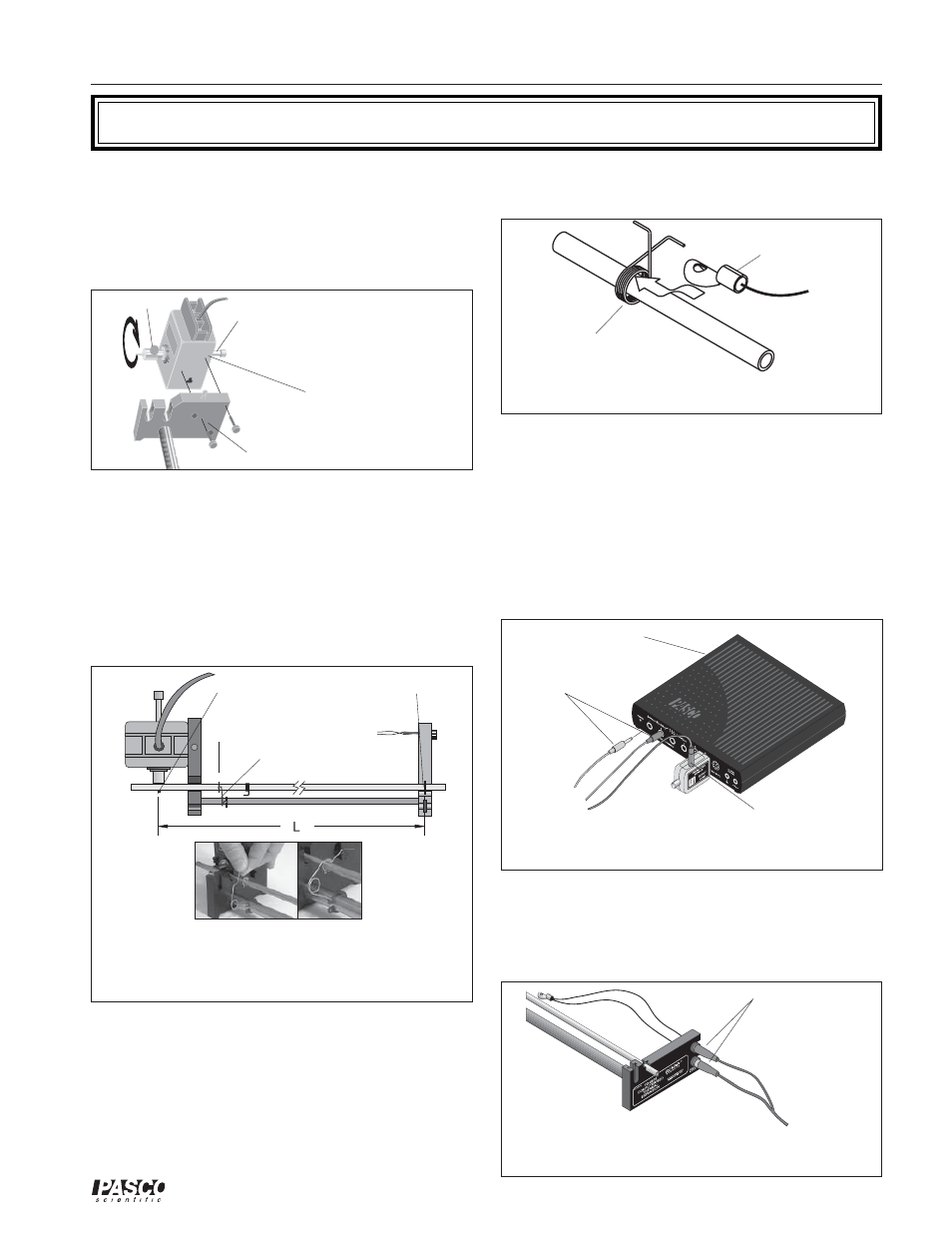
rotary motion
sensor pin
spring clip
C
thermistor
capture
thermal rod
Apparatus Setup
1. Attach the Rotary Motion Sensor (RMS) to
the large end block on the apparatus. Use
the black thumb screws to attach the RMS to
the holes in the larger of the black end blocks
(See Figure 1). Place the pinion onto the shaft
of the RMS and rotate clockwise to tighten.
Figure 3: Placing the Thermistor lug (with thermistor)
on the metal rod.
2. Align and anchor the copper rod in the expan-
sion base (Figure 2). The stainless steel ring on
the rod fits into the groove on the labeled mount-
ing block, and the metal rod lies over and presses
against the pin on the Rotary Motion Sensor.
Hook the spring clip (on the support rod) over the
top metal rod and to the left side of the grip ring.
(Note: This anchors the rod and establishes the
zero position).
Figure 1: Mounting
the Rotary Motion
Sensor to the end block
of the Apparatus
Figure 2: Aligning and anchoring the metal rod in the
expansion base.
Rotary Motion
Sensor
end block
4. Plug the Sensors into the Interface. Insert the
DIN connector of the Thermistor Sensor into an
analog channel in the ScienceWorkshop inter-
face. Attach the stereo plug of the Thermistor
Sensor cable into the 10 k
Ω
jack on the Ther-
mistor Sensor. Insert the banana plugs for the
Rotary Motion Sensor into digital channels 1 and
2 (yellow=channel 1, black=channel 2) on the
ScienceWorkshop interface.
3. Attach the Thermistor lug beneath the spring
clamp on the metal rod. With one hand, place
the Thermistor lug over the top of the metal rod,
such that the concave side fits snugly over the
rod (Figure 3). Align the lug with the axis of the
rod, so that there is maximum contact between
the lug and the rod. With your other hand, press
the ends of the spring clamp together. Slide the
Figure 4: Plugging the Thermistor and Rotary Motion
Sensors into the ScienceWorkshop Interface
Insert the red and
black banana
plugs here.
5. Attach the Rotary Motion Sensor leads to
the apparatus. Insert the red and black
banana plugs into the jacks on the endblock
(the one with the Thermistor label).
Figure 5: Attaching the banana plugs from the Ther-
mistor Sensor to the end block of the apparatus
interface
cables to the Rotary
Motion Sensor
Thermistor
Sensor
spring
shaft
pinion
retaining ring
grip ring
3.5 Stereo Plug
lug underneath the capture spring to attach the
thermistor lug beneath the clamp.
(see Detail A)
Detail A