D. set up an example output signal, E. view the output signal in a capstone display – PASCO UI-5000 850 Universal Interface Instruction Manual User Manual
Page 16
850 Universal Interface
UI-5000
®
®
16
012-12355A
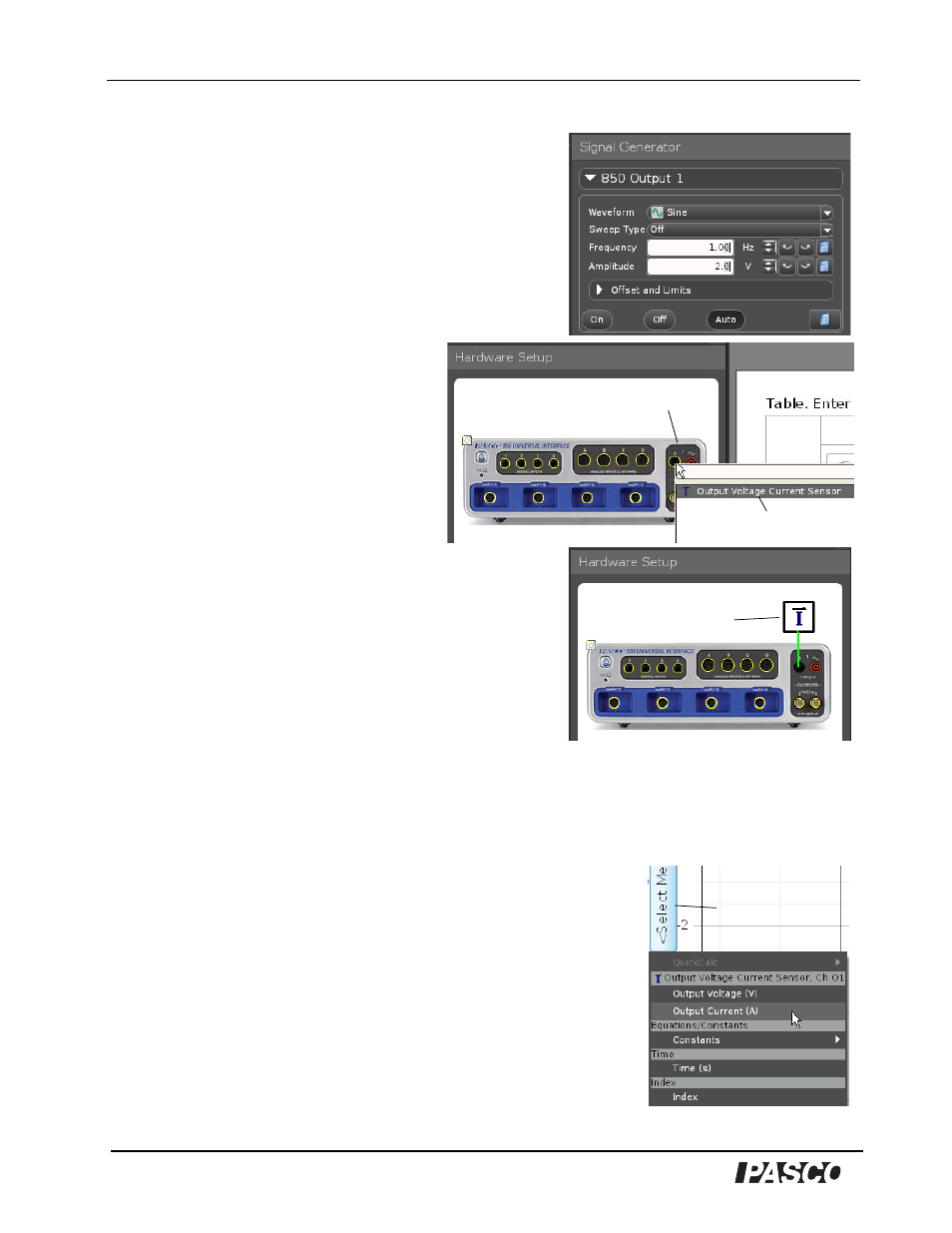
D. Set Up an Example Output Signal
1. Use the Signal Generator panel to set up an output
signal. For this example, leave the Waveform as Sine,
and the Sweep Type as Off, but change the
Frequency to 1 Hz and the Amplitude to 2 V.
2. Click Auto so the Signal Generator will output the
signal while you record data.
3. Click the Setup button in the Tools
palette to open the Hardware Setup
panel.
4. Click the left-hand banana jack of
Output 1 in the picture of the 850
Universal Interface to open the sensor
menu.
5. In the menu, click
Output Voltage Current Sensor.
• The icon of the Voltage Current Sensor appears with
the picture of the interface in the Hardware Setup
panel.
E. View the Output Signal in a Capstone Display
1. Set up a Graph display in the Workbook page.
2. Use the Horizontal Axis Measurement Selection Menu
to select Time for the horizontal axis.
3. Click the Vertical Axis Measurement Selection Menu. Notice that the menu shows choices for
the output signals.
• The choices under Output Voltage Current Sensor, Ch 01
are Output Voltage (V) and Output Current (A).
4. Select Output Voltage (V) for the vertical axis.
5. Once the Graph display is set up to show Output Voltage on
the vertical axis and Time on the horizontal axis, click Record
to begin collecting data.
• The Record control changes to Stop, and data points appear
in the Graph display.
Output 1
Menu choice
Voltage Current
Sensor icon
Vertical axis
measurement
selection menu