Mr. Gasket 12S Micro-Electric Fuel Pump User Manual
Installation instructions
1
Mr. Gasket www.mr-gasket.com
FOrM 12s42s 11/12
INSTALLATION INSTRUCTIONS
O.E. REPLACEMENT (MICRO) ELECTRIC FUEL PUMPS
Mr. Gasket Part No. 12S and 42S
GeNeraL INFOrMatION
The Mr. Gasket (Micro) Electric Fuel Pumps #12S and #42S
are gravity feed pumps designed for original equipment
replacement on carbureted cars, trucks, industrial equip-
ment and farm equipment, including lawn and garden. It
also works for fuel transfer systems in gasoline applications
as well as a booster pump for an existing mechanical fuel
pump. Pump is self-priming, with a two bolt and two wire
installation. Average 2 amp draw at maximum delivery.
#12S is a universal design for most domestic 4, 6 and 8
cylinder carburetor applications. Operating fuel pressure
range for #12S is 4 – 7 PSI and flow is 35 GPH.
#42S is a universal design for most import 4 and 6 cyl-
inder carburetor applications. Operating fuel pressure
range for #42S is 2 – 3.5 PSI and flow is 28 GPH.
MOUNtING PrOCeDUre
step 1
Make sure the fuel tank is very close to empty. Drain if
needed. Inspect the current fuel line – if it is cracking,
replace it with a new fuel rated hose. Install supplied
in-line filter to prevent small particles from entering the
pump. We highly recommend installing a filter as well
between the carburetor and fuel pump to prevent small
particles from entering the carburetor. If you choose to
no longer use your mechanical fuel pump, make sure
to install a block-off plate or plug the pump inlet and
outlets. All fuel line connections should be leak-proof.
step 2
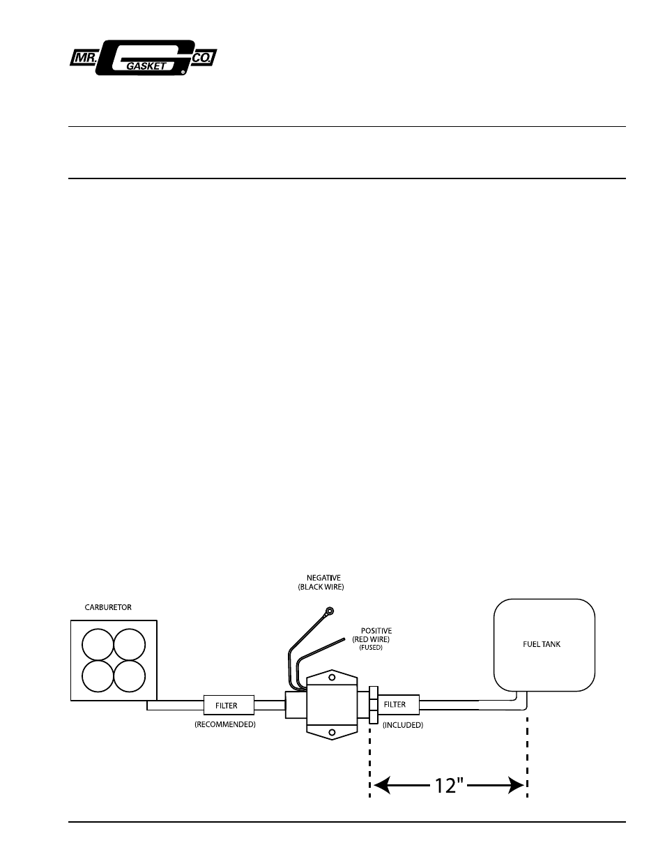
Mount the pump about 12” from the fuel tank and as
close to the lowest level of the tank to ensure proper
fuel supply. Refer to Figure 1. Make sure mounting
area is clean of all rust, paint and grease.
step 3
Using the pump mounting bracket as a template, drill
two 7/32” holes. Next, use the supplied self-tapping
bolts and star washers to secure the pump and
ground lead to the frame. Always mount the pump in
a location that allows you to add the safety nuts provided.
Install the supplied filter in the pump inlet and install
outlet fitting using thread sealer and tighten to 10-ft-lbs.
NOte: Never install pump in engine compartment.
step 4
Attach the hose to the inlet side of the supplied filter us-
ing automotive quality hose clamps. Some tank outlets
may have 3/8” instead of the supplied 5/16” fittings.
You may need to purchase one 3/8” barb x 1/8” NPT
x 3/8” length. If using 3/8” fitting, you may need to
purchase a 3/8” filter. DO NOT USE PUMP WITHOUT
A FILTER. Install the correct size fuel line from the outlet
port on the fuel pump to the factory metal fuel line going
to the engine bay. If no fuel line exists, fabricate a hard
line from the pump to the engine compartment.
NOte:
Never run rubber fuel line from the rear of the vehicle
to the front. always minimize use of rubber hose.
When possible, use steel hard line.
READ ALL INSTRUCTIONS CAREFULLY BEFORE BEGINNING INSTALLATION. RECOMMENDED FOR ORIGINAL EQUIPMENT REPLACEMENT
AND NEGATIVE GROUND SYSTEMS ONLY. NOT FOR USE WITH FUEL INJECTED SYSTEMS, HIGH PERFORMANCE OR MODIFIED ENGINES,
AIRCRAFT OR MARINE APPLICATIONS OR DIESEL FUEL. A FUEL PRESSURE REGULATOR IS HIGHLY RECOMMENDED.
FIGUre 1: