Liquid Controls SCAMP User Manual
Page 9
9
COMPUTING & PROGRAMMING MULTI-POINT CALIBRATION DATA (Cont.)
♦ Next, calculate meter error, as follows.
% Error = (Prover volume-Meter volume) x 100
Prover volume
Example:
% Error =
100.15 -100.17 x 100 = -0.01997%
100.15
♦ WITH NO FLOW THROUGH THE METER AND STILL IN THE FUNCTION WHERE
THE PULSE RATE WAS CAPTURED, set the Data Switches to specify the above-
calculated error at the given flow rate. The value entered must be in the range of -
3.000 to +3.000. Negative numbers are denoted by setting a “0” on the left-most
Data Switch (sw5). Using the above example, the error of -0.01997% would first be
rounded to 3 significant digits in accordance with Weights & Measures rules to
-0.020, and then entered on the Data Switches as “00203”, where the last digit is
used to establish left-shifting of the decimal point. Once the error value has been set
on the Data Switches, depress the Data Entry pushbutton to enter the value in
memory. The LED display will now scroll the new value, e.g. “F3704 P-0.02”.
♦ Perform the identical operations for additional flow rates by moving the Function
Switch to the “1” position (and then entering data), then to the “2” position, and so
forth, for a maximum of up to sixteen flow rates.
IMPORTANT: The multi-point calibrations computed and entered above are not
activated until the “0/1” jumper is moved back to the “0” position and the Function Switch
is returned to either the Function 0 (gross measurement mode) or Function 1 through A
(net measurement mode).
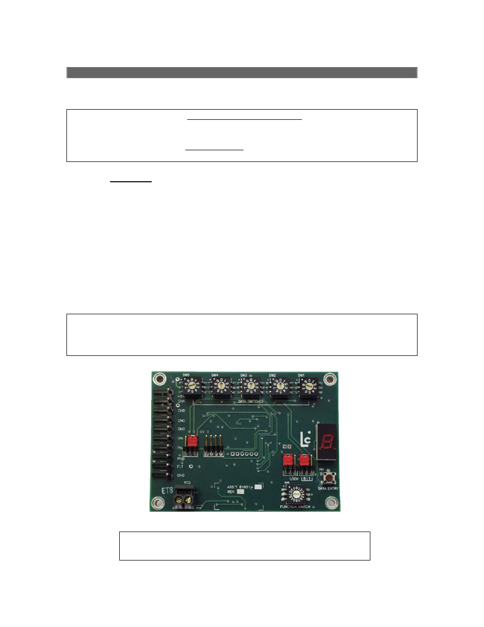
Circuit board illustration for identifying user switches and
jumpers referenced in instructions.