Asus 1U Rackmount Barebone Server RS120-E3 (PA4) User Manual
Page 65
A S U S R S 1 2 0 - E 3 / P A 4
A S U S R S 1 2 0 - E 3 / P A 4
A S U S R S 1 2 0 - E 3 / P A 4
A S U S R S 1 2 0 - E 3 / P A 4
A S U S R S 1 2 0 - E 3 / P A 4
4 - 1 7
4 - 1 7
4 - 1 7
4 - 1 7
4 - 1 7
•
S y s t e m p o w e r L E D ( G r e e n 3 - p i n P L E D )
S y s t e m p o w e r L E D ( G r e e n 3 - p i n P L E D )
S y s t e m p o w e r L E D ( G r e e n 3 - p i n P L E D )
S y s t e m p o w e r L E D ( G r e e n 3 - p i n P L E D )
S y s t e m p o w e r L E D ( G r e e n 3 - p i n P L E D )
This 3-pin connector is for the system power LED. Connect the
chassis power LED cable to this connector. The system power LED
lights up when you turn on the system power, and blinks when the
system is in sleep mode.
•
M e s s a g e L E D ( B r o w n 2 - p i n M L E D )
M e s s a g e L E D ( B r o w n 2 - p i n M L E D )
M e s s a g e L E D ( B r o w n 2 - p i n M L E D )
M e s s a g e L E D ( B r o w n 2 - p i n M L E D )
M e s s a g e L E D ( B r o w n 2 - p i n M L E D )
This connector is for the message LED cable that connects to the
front panel message LED. The message LED indicates the booting
status. The LED blinks when the system is in the boot process until
the operating system is loaded.
•
S y s t e m w a r n i n g s p e a k e r ( O r a n g e 4 - p i n S P E A K E R )
S y s t e m w a r n i n g s p e a k e r ( O r a n g e 4 - p i n S P E A K E R )
S y s t e m w a r n i n g s p e a k e r ( O r a n g e 4 - p i n S P E A K E R )
S y s t e m w a r n i n g s p e a k e r ( O r a n g e 4 - p i n S P E A K E R )
S y s t e m w a r n i n g s p e a k e r ( O r a n g e 4 - p i n S P E A K E R )
This 4-pin connector is for the chassis-mounted system warning
speaker. The speaker allows you to hear system beeps and warnings.
•
H a r d d i s k d r i v e a c t i v i t y L E D ( R e d 2 - p i n H D D L E D )
H a r d d i s k d r i v e a c t i v i t y L E D ( R e d 2 - p i n H D D L E D )
H a r d d i s k d r i v e a c t i v i t y L E D ( R e d 2 - p i n H D D L E D )
H a r d d i s k d r i v e a c t i v i t y L E D ( R e d 2 - p i n H D D L E D )
H a r d d i s k d r i v e a c t i v i t y L E D ( R e d 2 - p i n H D D L E D )
This 2-pin connector is for the HDD Activity LED. Connect the HDD
Activity LED cable to this connector. The IDE LED lights up or flashes
when data is read from or written to the HDD.
1 4 .
1 4 .
1 4 .
1 4 .
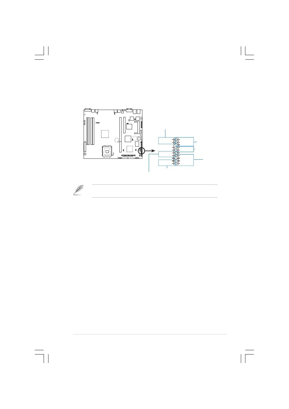
1 4 . System panel connector (20-pin PANEL1)
S y s t e m p a n e l c o n n e c t o r ( 2 0 - p i n P A N E L 1 )
S y s t e m p a n e l c o n n e c t o r ( 2 0 - p i n P A N E L 1 )
S y s t e m p a n e l c o n n e c t o r ( 2 0 - p i n P A N E L 1 )
S y s t e m p a n e l c o n n e c t o r ( 2 0 - p i n P A N E L 1 )
This connector supports several chassis-mounted functions.
The sytem panel connector is color-coded for easy connection. Refer to
the connector descriptions below for details.
P5MT-R
®
P5MT-R System panel connector
PANEL1
MLED-
GND
NC
POWERBTN#
+5V
GND
GND
NC
POWERLED+
HDLED+
GND
HDLED-
POWERLED-
MLED+
NMIBTN#
GND
RESETBTN#
SPKROUT
GND
P o w e r L E D
P o w e r L E D
P o w e r L E D
P o w e r L E D
P o w e r L E D
S y s t e m
S y s t e m
S y s t e m
S y s t e m
S y s t e m
w a r n i n g
w a r n i n g
w a r n i n g
w a r n i n g
w a r n i n g
s p e a k e r
s p e a k e r
s p e a k e r
s p e a k e r
s p e a k e r
H D D L E D
H D D L E D
H D D L E D
H D D L E D
H D D L E D
R e s e t b u t t o n
R e s e t b u t t o n
R e s e t b u t t o n
R e s e t b u t t o n
R e s e t b u t t o n
Message LED
Message LED
Message LED
Message LED
Message LED
P o w e r b u t t o n
P o w e r b u t t o n
P o w e r b u t t o n
P o w e r b u t t o n
P o w e r b u t t o n