Ram 300, Pushbutton controls, Master/slave installation – Controlled Products Systems Group RAM300 User Manual
Page 13
RAM 300
RAMSET
11
www.ramsetinc.com
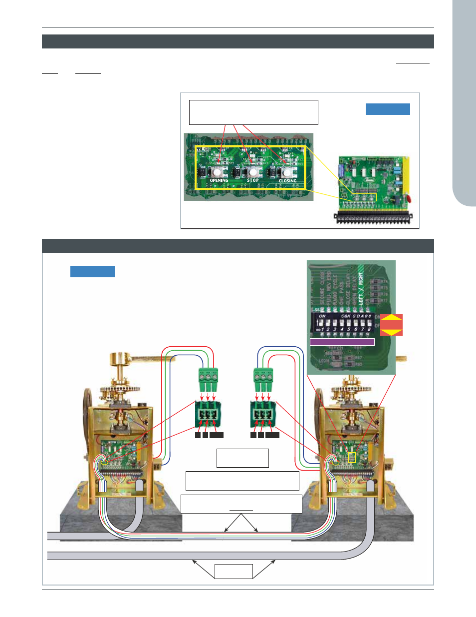
Use 3-stranded, shielded wires
(not supplied) from Master to Slave.
Use jumper
JP7 to JP7
Route low-voltage wires for Master/Slave
in a conduit separate from power.
Conduit
for power
Set Dip Switch (C8) “Slave Mode” to ON for
slave operation.
(RH) Right Hand operation requires Dip Switch
(C7) “Left/Right” to be ON.
Dip Switch “C”
A B COM
A B COM
SELECT
ON
OFF
Figure 12
L.E.D.’s light up when Opening,
Closing or Stopped
“Intelligate” Control Board
PUShBUTTON CONTROLS
Three pushbuttons are located under the dip switches for operation of the gate (see Figure 11). The opening,
stop and closing buttons can be utilized to set limit switches and verify proper system operation when install-
ing or servicing an operator.
Opening
Pressing this button will cause
the gate to open.
Stop
Pressing this button will cause
the gate to stop moving.
Closing
Pressing this button will cause
the gate to close.
Reset E.R.d. board
Push all three pushbuttons for
approximately 5 seconds. All
three L.E.D.’s should blink.
Figure 11
MASTER/SLAvE INSTALLATION