Installation – Controlled Products Systems Group CSW24V User Manual
Page 18
16
INSTALLATION
INSTALLATION CONTINUED...
INSTALLATION CONTINUED...
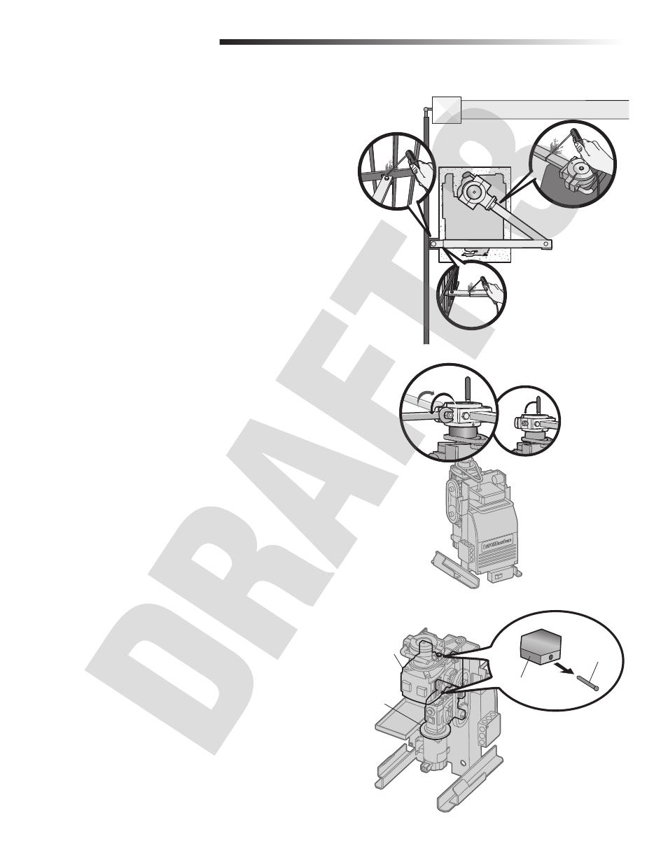
WELD THE OPERATOR ARM
Once the operator arm measurements are verified:
1
Weld the gate bracket to the gate.
2
Weld the short arm section.
3
Weld the long arm section.
4
Remove the set screws from the arm.
NOTE: Completely weld around the outer tubing and bracket.
3
1
2
SECURE THE OPERATOR ARM TO THE OUTPUT SHAFT
1
Adjust the nuts on the operator arm so the operator arm fits snug on the
output shaft yet still allows enough room to swivel (the handle must be in a
90° position).
2
Tighten the handle by pushing it down. Test to make sure the operator arm
does not slip on the output shaft.
1
2
REMOVE THE PINS FROM THE VENT PLUGS
1
Remove the pin from the vent plug on both the top and bottom gear boxes.
Pin
Top Gear Box
Bottom Gear Box
Vent Plug
- GNC-1 (1 page)
- -108712 (33 pages)
- 1044372 (28 pages)
- 1042071277 (28 pages)
- 104207177 (28 pages)
- 104301 (30 pages)
- 10441811 (29 pages)
- 1044182 (28 pages)
- 1044682 (28 pages)
- 104471 (28 pages)
- 104572 (24 pages)
- 104572 (27 pages)
- 10468583 (36 pages)
- 1049062 (17 pages)
- 106753 (28 pages)
- 108758 (40 pages)
- 109773 (19 pages)
- 10978021 (6 pages)
- 109902 (27 pages)
- 1150-080 (30 pages)
- 1600 (17 pages)
- 1650ETL (23 pages)
- 1650ETL-1K (32 pages)
- 1602-091 (42 pages)
- 1601-081 (36 pages)
- 1602-091 (42 pages)
- 1603-166 (38 pages)
- 1603-166 (42 pages)
- 1603-166 (40 pages)
- 444 XS ST (98 pages)
- 222X383 (84 pages)
- 3020HX (24 pages)
- 3600ETL-1K (36 pages)
- 4500SW (32 pages)
- 6004-080 (34 pages)
- 6002-080 (32 pages)
- 6003-080 (22 pages)
- 6100-083 (56 pages)
- 6100-083 (2 pages)
- 6100-083 (46 pages)
- 6300-087 (59 pages)
- 6300-087 (52 pages)
- 6400-080 (28 pages)
- 6500-087 (48 pages)
- 6500-087 (46 pages)