Electrical installation, G-5 x-9 & i-8 – Controlled Products Systems Group ECUMSING5 User Manual
Page 18
VIKING TECHNICAL SUPPORT 1.800.908.0884
1 6
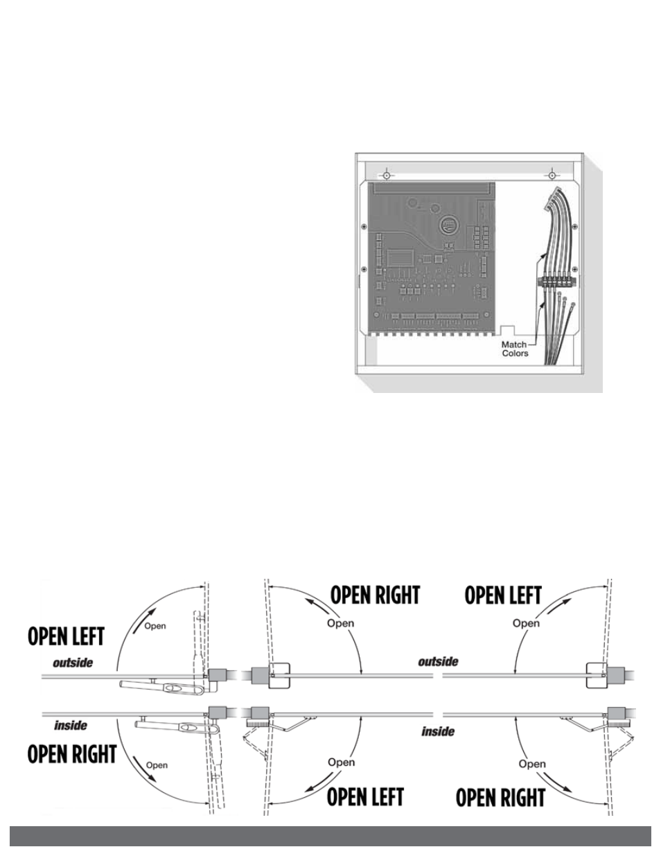
Motor Harness
NOTE:
Refer to the gate operator’s Installation Manual (G-5, X-9 or i-8) for specific
instructions on how to connect the gate operator’s wiring harness to the operator.
STEP 3
Connect the “Motor Harness” to the Control Board.
For G-5 operator
a. “OPEN RIGHT” Connector if the gate opens to the INSIDE
(pull to open).
b. “OPEN LEFT” Connector if the gate opens to the OUTSIDE
(push to open).
For X-9 and i-8 operators
a. “OPEN RIGHT” Connector if the gate opens
Inside to the Right or Outside to the Left.
b. “OPEN LEFT” Connector if the gate opens
Inside to the Left or Outside to the Right.
ELECTRICAL INSTALLATION
STEP 1
Connect the wires from the operator’s
wiring harness to the terminal block
mounted next to the control board.
Match wire colors to the terminal block.
!
Tip:
If this controller is an i-8 model
ECU, the blue and black wires from
the operator’s wiring harness are only
required to be connected.
STEP 2
Connect the ground wire, (bare or non-
insulated wire) from the operator’s wiring
harness, to both the Chassis of the ECU
and the gate operator.
G-5
X-9 & i-8