Important installation information – Controlled Products Systems Group ECUMSING5 User Manual
Page 15
VIKING TECHNICAL SUPPORT 1.800.908.0884
1 3
!
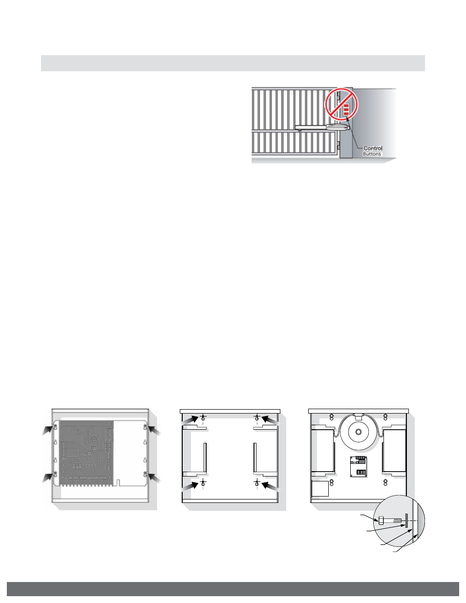
WARNING: dO NOT allow pedestrian use of this gate.
IMPORTANT INSTALLATION INFORMATION
Locate Control Buttons:
1. Within sight of the gate,
2. At a minimum height of 5 feet
so small children are not able to
reach it; and
3. At least 6 feet away from all
moving parts of the gate.
Specifications
Power Requirements:
115v / 230v AC (4 amp / 2 amp)
Single Phase (50 Hz / 60 Hz)
24v
AC
/
DC
Solar
24v
80w
Mounting surface
Control Box
sealed Washer
(supplied with Unit)
Mounting Fastener
(Customer supplied)
STEP 1
Disconnect the Siren
and Stop ButtonLeads
from the Control Board.
Remove the Control
Board Mounting Plate.
The plate is held in the
box by four screws.
STEP 2
Position the ECU Box
in the desired place
and mark the mounting
holes. Prepare the holes
to receive the anchors/
fasteners.
NOTE: Anchors are Not
Supplied.
STEP 3
Position the ECU Box
and secure it to the
mounting surface using
the Sealed Washers
provided (rubber side
of the washers against
the inside of the control
box).
ECU Box Installation
!
WARNING: If the control box is not mounted properly
it may fall, causing damage and/or injury. The Electronic
Control Unit (ECU) weight is approximately 40 lbs.
Be sure that the substrate being mounted to and the
fasteners being used are appropriate to support the
weight of the control box.