Accessory connections, Uv v, Common n/c n/o – Controlled Products Systems Group AOMSL90DC User Manual
Page 13
12
C
C
Power
Detect
Loop Fail
Reset
2
1
0
0
SENS.
LEVEL
BOOST ON
PULSE
FREQ.
0
0
OFF
PRES
2
1
1
2
3
4
5
6
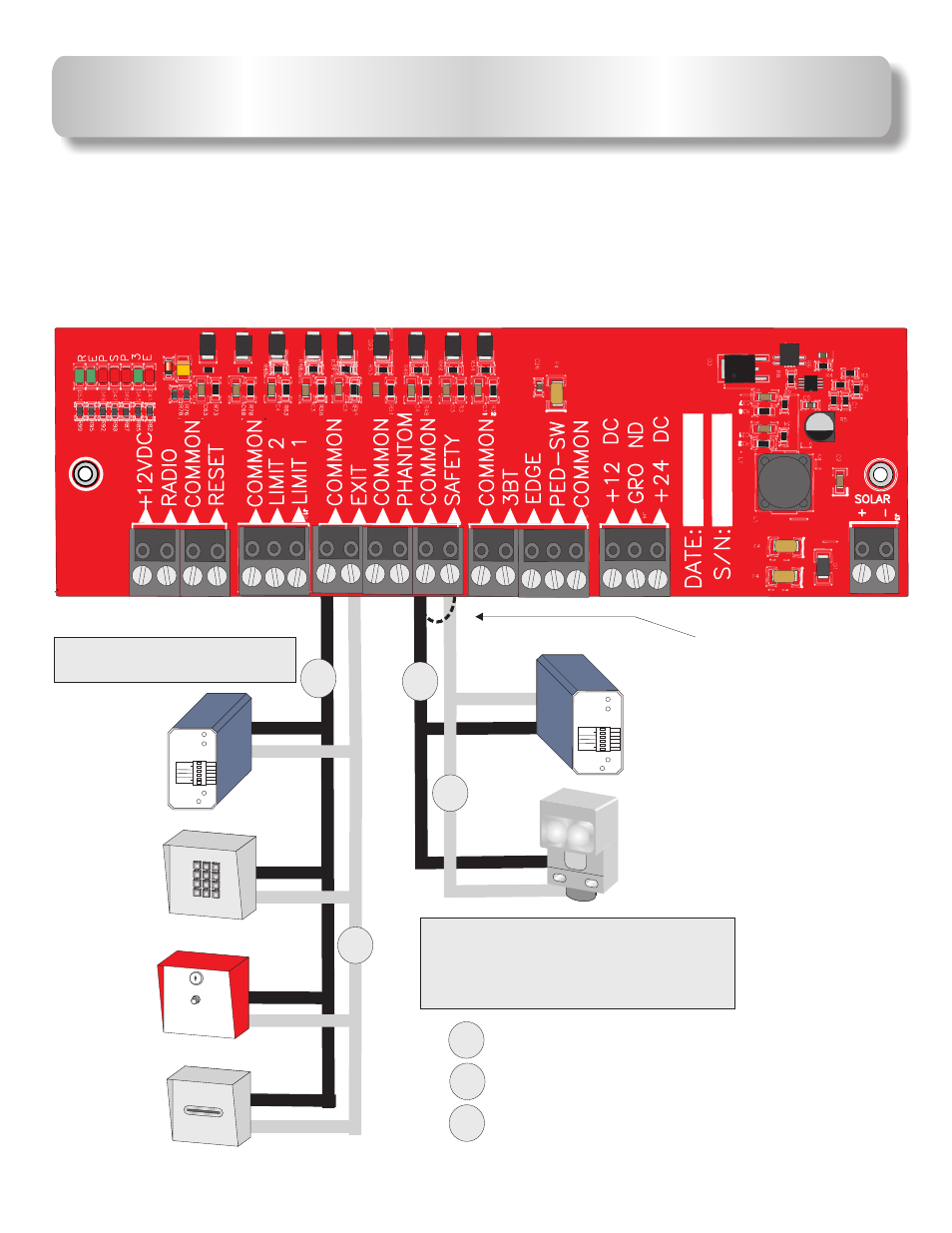
SAFETY Loop
Detector
PHOTO Beam
EXIT
Loop
Detector
Keypad
or
Telephone
Push Button
or
Fire Box
Card Reader
or
Key Switch
See page 13 for connection of
multiple safety device wiring
diagram.
See page 14 for plugin loop
detector installation.
Remove wire jumper
from
when
a safety device is
installed.
SAFETY
ACCESSORY CONNECTIONS
AB
= NORMALLY OPEN CONTACT
N/C
= NORMALLY CLOSED CONTACT
C
= COMMON
N/C
N/O
The circuit board
output provides up to
mAmps of power for accessories.
More than two or three accessories will require a separate power supply.
12 or 24VDC Accessories only.
12 or 24VDC
500
NOTE:
Power
Detect
Loop Fail
Reset
2
1
0
0
SENS.
LEVEL
BOOST ON
PULSE
FREQ.
0
0
OFF
PRES
2
1
1
2
3
4
5
6
1
ABC
2
DEF
3
GHI
4
JKL
5
MNO
6
PQRS
7
TUV
8
WXYZ
9
TONE
*
OPER
0
#
N/O
C8RB
LMC64
82AIM
1002
1002
1002
1002
1002
1002
1002
1002
1002
1002
1002
1002
1002
1002
1212
2402
3002
6040
1001
1001
1001
1501
1501
1501
1501
1501
1501
1501
1501
1501
1501
1501
1501
1501
1501
MAAF
S21B
33 HFK 5GN
802
360G
B
ON
DR127-330
43CL07 E
U
V
V