Radio receiver installation, Radio receiver connections, Multi- code – Controlled Products Systems Group AOMSW300 User Manual
Page 26
47
ON
514
GDE
ON
514
GDE
ON
514
GDE
ON
514
GDE
Multi-
Code
3
2
1
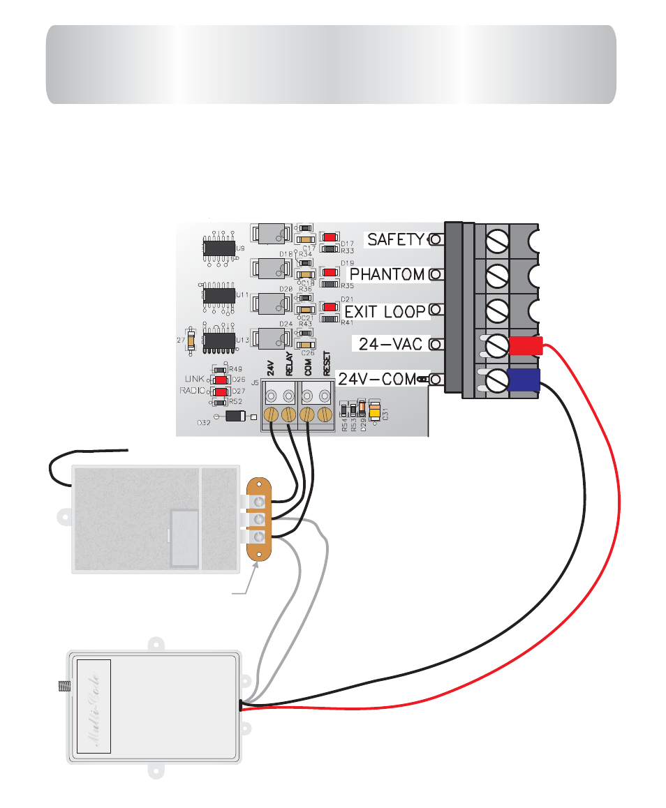
3 = 24V
2 = Relay
1 = Common
Receiver terminal strip
located outside control
box.
RADIO RECEIVER CONNECTIONS
3 wire receiver mounts on receiver strip outside control box as shown
below.
4 wire receiver :connect the two grey wires to
&
terminals on receiver
strip outside control box. Connect black wire to
and red wire
to
on main
board terminal strip as shown below.
1
2
24 V-COM
24VAC
control
4 wire 24VAC
Radio Receiver
3 wire 24VAC
Radio Receiver
This manual is related to the following products:
See also other documents in the category Controlled Products Systems Group Safety:
- GNC-1 (1 page)
- -108712 (33 pages)
- 1044372 (28 pages)
- 1042071277 (28 pages)
- 104207177 (28 pages)
- 104301 (30 pages)
- 10441811 (29 pages)
- 1044182 (28 pages)
- 1044682 (28 pages)
- 104471 (28 pages)
- 104572 (24 pages)
- 104572 (27 pages)
- 10468583 (36 pages)
- 1049062 (17 pages)
- 106753 (28 pages)
- 108758 (40 pages)
- 109773 (19 pages)
- 10978021 (6 pages)
- 109902 (27 pages)
- 1150-080 (30 pages)
- 1600 (17 pages)
- 1650ETL (23 pages)
- 1650ETL-1K (32 pages)
- 1601-081 (36 pages)
- 1602-091 (42 pages)
- 1602-091 (42 pages)
- 1603-166 (38 pages)
- 1603-166 (42 pages)
- 1603-166 (40 pages)
- 444 XS ST (98 pages)
- 222X383 (84 pages)
- 3020HX (24 pages)
- 3600ETL-1K (36 pages)
- 4500SW (32 pages)
- 6004-080 (34 pages)
- 6002-080 (32 pages)
- 6003-080 (22 pages)
- 6100-083 (2 pages)
- 6100-083 (46 pages)
- 6100-083 (56 pages)
- 6300-087 (52 pages)
- 6300-087 (59 pages)
- 6400-080 (28 pages)
- 6500-087 (48 pages)
- 6500-087 (46 pages)