Mag/solenoid lock installation, Magnetic/solenoid lock connections – Controlled Products Systems Group AOMSW300 User Manual
Page 25
45
ON
514
GDE
ON
514
GDE
ON
514
GDE
ON
514
GDE
ON
514
GDE
ON
514
GDE
ON
514
GDE
1
234
56
78
1
2
3
4
5
6
7
8
-----------------------OPEN------------------------
TIMER
RADIO
OSC
1-PASS
SLAVE
BRAKE
SPARE
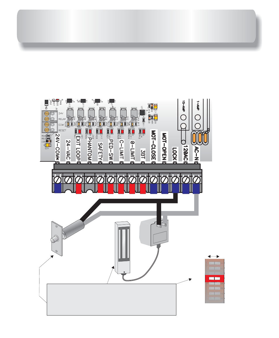
LOCK
OFF
ON
For MAGNETIC LOCK set “
” Dip
Switch to the “
” Position.
For SOLENOID LOCK set “
” Dip
Switch to the “
” Position.
LOCK
ON
LOCK
OFF
MAG
LOCK
SOLENOID
LOCK
Step Down
Transformer
MAGNETIC/SOLENOID LOCK
CONNECTIONS
Magnetic lock installation requires a step down transformer with appropriate
voltage for the specific lock accessory.
and
from terminal strip supply 110 volts to power the transformer
and control the locks’. Connect low voltage wires from transformer directly to
the lock as shown below. Only two wires needed for the installation. No relay
wires required.
AC-N
LOCK
This manual is related to the following products: