Loops layout, Swinger loop layout, Normally closed contacts normally open contacts – Controlled Products Systems Group AOMSW300 User Manual
Page 17: Exit loop
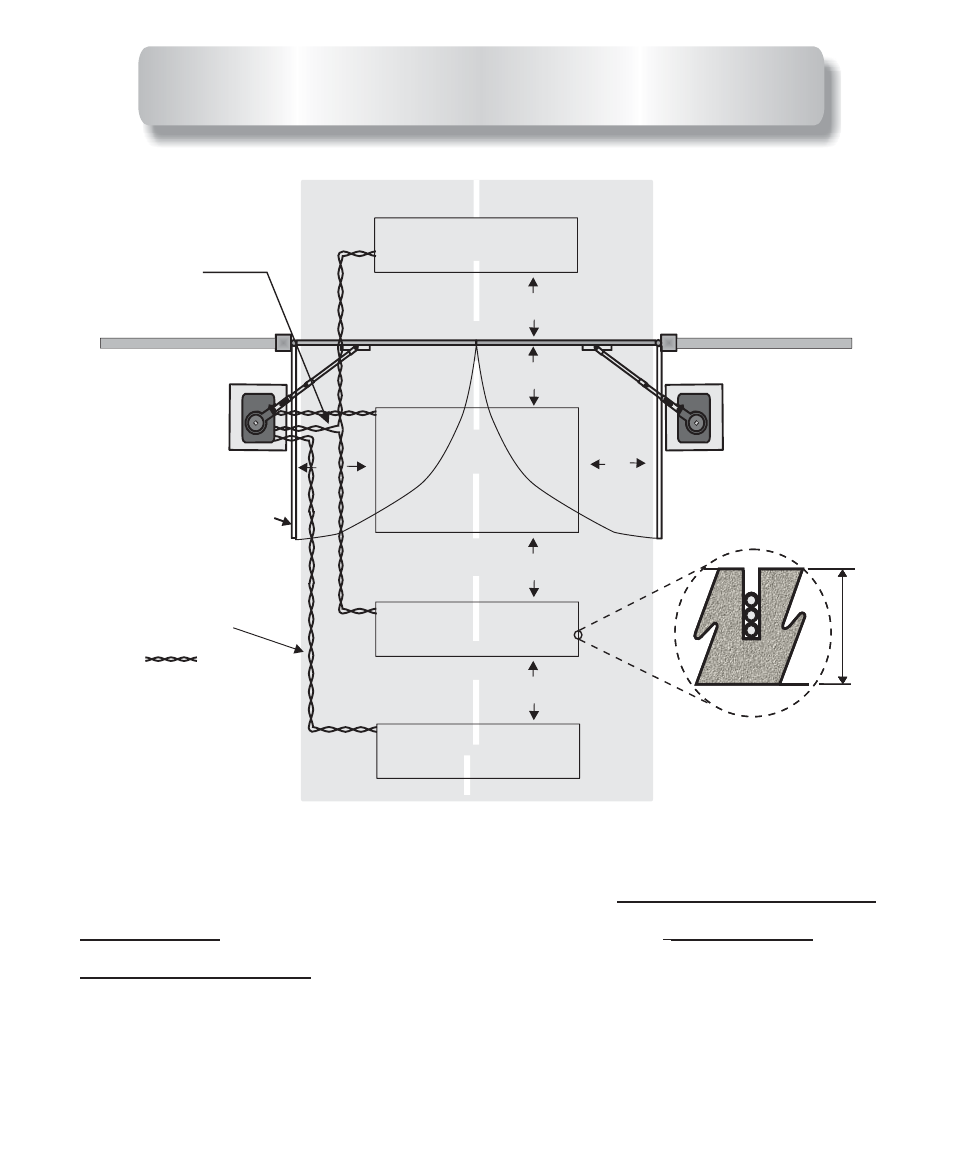
29
This is a normal loop layout. Remember when connecting to
an All-O-Matic circuit board you use the
for your safety loop detector and
from the exit loop. You must twist your
wires from your exit point of the saw cut all the way to the
circuit board, no exceptions.
normally closed
contacts
normally
open contacts
SWINGER LOOP LAYOUT
Outside Safety loop
Outside Safety loop
Inside Safety loop
Inside Safety loop
Center Phantom loop
Center Phantom loop
5F
T
5
FT
5F
T
5
FT
5 FT
5 FT
5 FT
5 FT
5F
T
5
FT
5F
T
5
FT
Gate in open
position
Gate in open
position
Exit loop
Exit loop
1/4 IN
1/4 IN
1
1/2
IN
TWISTED 6
TURNS
PER FOOT
WIRED IN
SERIES
WHEN USED
This manual is related to the following products: