Radio receiver hookup, Radio receiver connections, Multi-code – Controlled Products Systems Group AOMSL100 User Manual
Page 23
ON
514
GDE
ON
514
GDE
ON
514
GDE
ON
514
GDE
Multi-Code
3
2
1
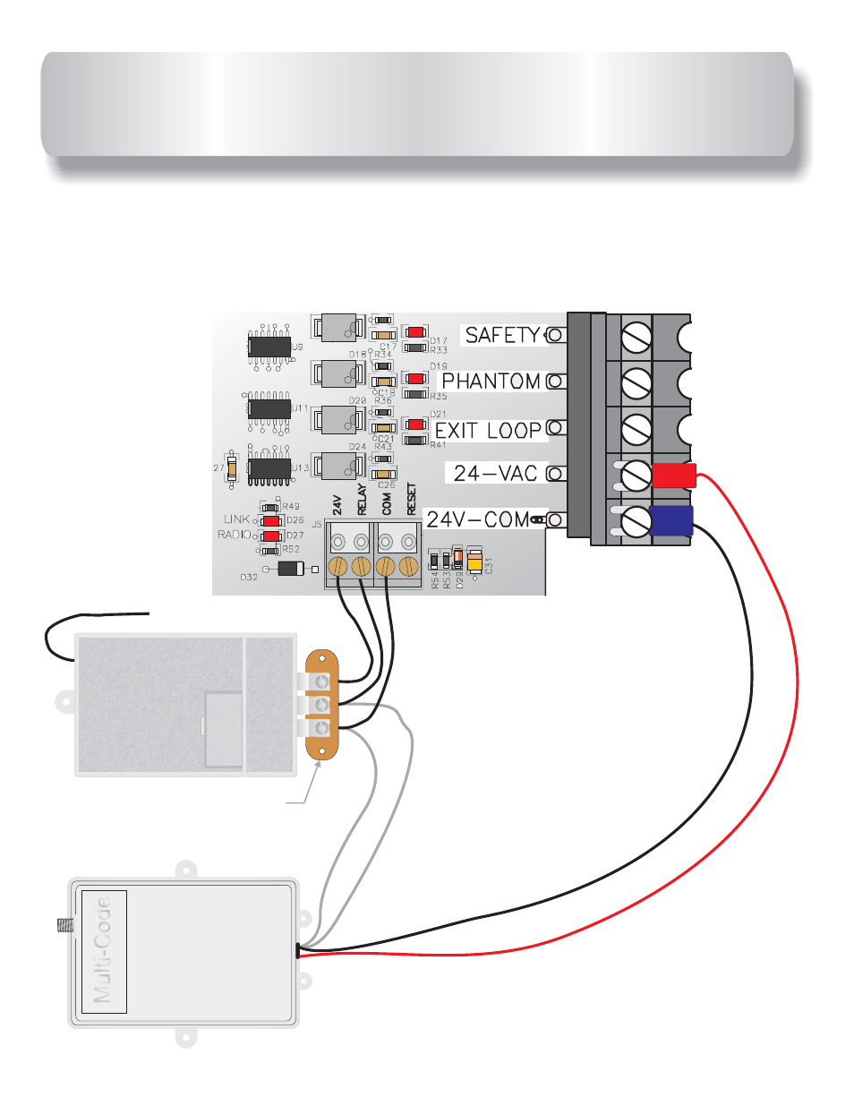
3 = 24V
2 = Relay
1 = Common
Receiver terminal strip
located outside control
box.
RADIO RECEIVER CONNECTIONS
3 wire receiver mounts on receiver strip outside control box as shown below.
4 wire receiver :connect the two grey wires to
&
terminals on receiver
strip outside control box. Connect black wire to
and red wire
to
on main
board terminal strip as shown below.
1
2
24 V-COM
24VAC
control
4 wire 24VAC
Radio Receiver
3 wire 24VAC
Radio Receiver
43
This manual is related to the following products: