Accessory connections, 24v-com – Controlled Products Systems Group AOMSL100 User Manual
Page 15
ON
514514
GDE
ON
514
GDE
ON
514
GDE
ON
514
GDE
ON
514
GDE
ON
514
GDE
ON
514
GDE
Power
Detect
Loop Fail
Loop Fail
Reset
2
1
0
0
SENS.
SENS.
LEVEL
BOOST ON
BOOST ON
PULSE
PULSE
FREQ.
0
0
OFF
PRES
2
1
1
2
3
4
5
6
Power
Detect
Loop Fail
Loop Fail
Reset
2
1
0
0
SENS.
LEVEL
BOOST ON
PULSE
PULSE
FREQ.
0
0
OFF
PRES
PRES
2
1
1
2
3
4
5
6
C
C
C
C
C
C
C
C
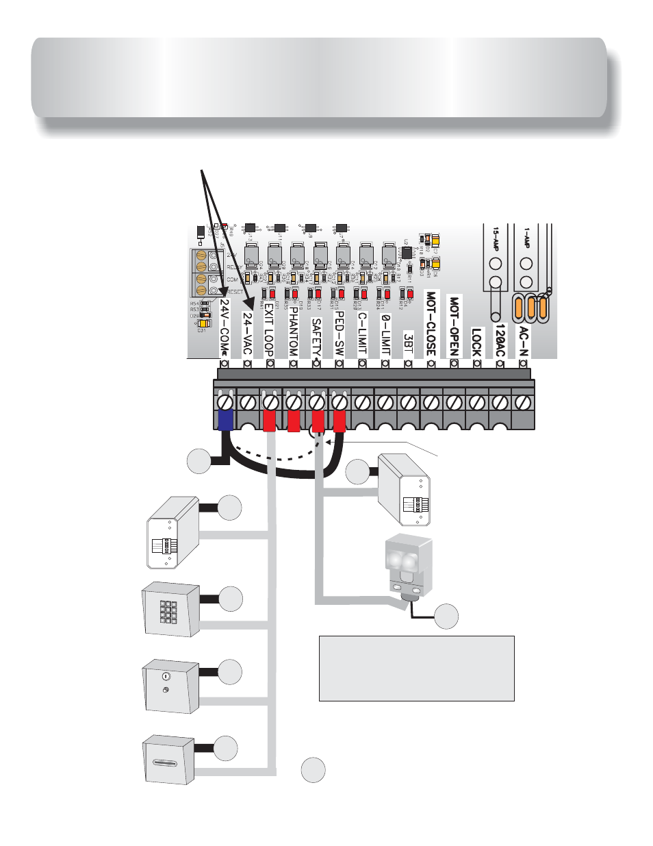
SAFETY Loop
Detector
PHOTO Beam
EXIT Loop
Detector
Keypad or
Telephone
Push Button or
Fire Box
Card Reader or
Key Switch
AB
See page 29 for connection of
safety device wiring diagram.
1
ABC
2
DEF
3
GHI
4
JKL
5
MNO
6
PQRS
7
TUV
8
WXYZ
9
TONE
*
OPER
0
#
Remove black jumper
from SAFETY when
a safety device is
installed.
= 24V-COM
ACCESSORY CONNECTIONS
The circuit board
output provides up to 700 mAmps of power for accessories. More
than two or three accessories will require a separate power supply.
24-VAC
27
This manual is related to the following products: