Controlled Products Systems Group 1550ETL-1K User Manual
Page 13
13
Auxiliary Inputs 1 (16) and 2 (18): These digital inputs may be connected to the digital outputs of accessories
and programmed to activate or control the gate operator in a number of different modes. Shorting pin 1 to pin 2
through a dry contact activates the programmed settings for these input. These inputs are programmed in the
“FUNCTION Auxiliary I/O” menu.
LOOP Input: (22) Dry contact input that can be programmed for an inductive safety loop or photo-eye detector.
Shorting the digital input to GND reverses a closing gate to the full open position. The opened gate is held
opened for as long as the LOOP input is active. (SAFETY)
LOOP 1 Input: (24) Dry contact input that can be programmed for an inductive safety loop or photo-eye detec-
tor. Activating the LOOP 1 input maintains an OPEN gate fully open and a CLOSED gate fully closed until deac-
tivated. (SHADOW) Setting the LOOP1 input to “Photo Mode” causes the moving gate to stop, then reopens the
gate when the LOOP1 input is deactivated.
LOOP 2 Input: (26) Dry contact input that can be programmed for an inductive safety loop or photo-eye detec-
tor. Activating the LOOP2 input (26) while the gate is opening cause the gate to close to the fully closed position.
This loop input is intended for use with safety sensors to prevent entrapment between the opening gate and an
adjacent wall or structure.
Edge Input: (28) This input may be configured as “DIGITAL” or “ANALOG” as required by the sensor type.
When configured as “DIGITAL”, this is a dry contact input; otherwise when configured as “ANALOG”, the input
must measure 8200ohms. When the input is activated it stops the gate regardless of direction of travel, momen-
tarily reverses it then stops.
Exit Input: (30) Dry contact input for a vehicle exit sensor. Opens gate from the closed position and holds gate
open with maintained input or reverses gate if closing.
Fire Input: (32) Dry contact input for a fire department control switch. Opens the gate and holds the gate open
until the control switch is deactivated. This input is “hold to run”. Auto-close is disabled when this input is activat-
ed. Also clears hard shutdown.
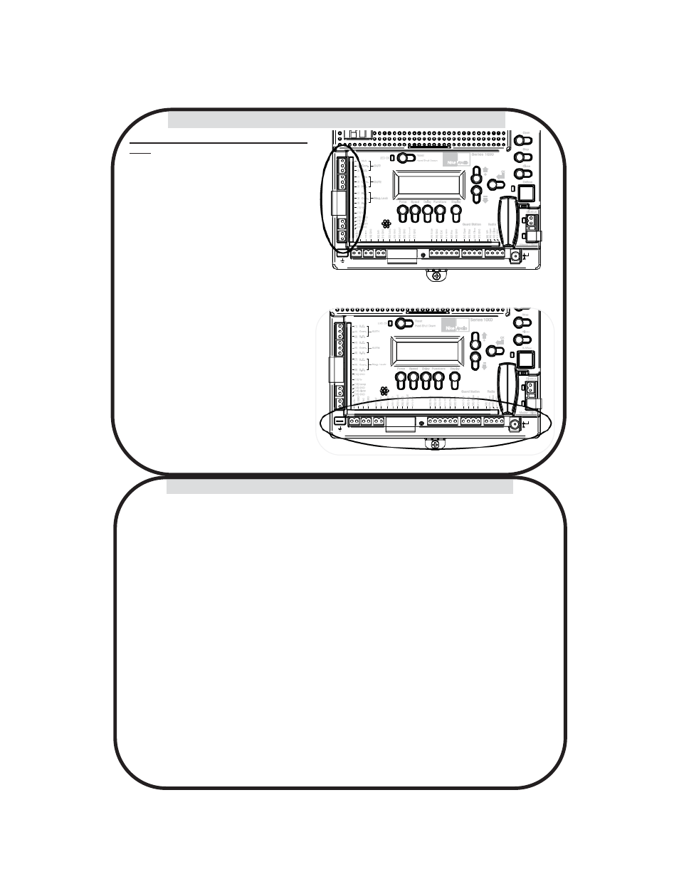
4 - OUTPUTS & INPUTS
Figure 18: INPUTS
Figure 17: BOARD OUTPUTS
Commercial Gate Operator Accessory Out-
puts:
OUT1 and OUT2: Individual, isolated relays
provide COMMON, NORMALLY OPEN, and
NORMALLY CLOSED dry contacts for switch-
ing accessories based on programming of the
“Auxiliary IO” function. These outputs are pro-
grammed in the “FUNCTION Auxiliary I/O”
menu.
Magnetic Lock: Provides fused power (1.85A
max) and isolated relay COMMON, NORMAL-
LY OPEN, and NORMALLY CLOSED dry con-
tacts for electrically powered and maintained
magnetic locks. The delay for magnetic lock
activation/deactivation may be adjusted from 0
to 5 seconds.
Lamp: Provides fused power (1.85A max) to
drive a flashing warning lamp to indicate gate
operation. This output is active when the gate
is operating (Opening and Closing). Sets the
amount of time the lamp accessory output is
activated prior to gate movement. Settings from
0 to 5 seconds with a step of 0.5 seconds.
Alarm: Provides fused power (0.5A @ 12VDC)
to drive an alarm siren to signal the occurrence
of a hard shutdown, caused by 2 consecutive
entrapment events (signals). This alarm output
is reset by pressing the “Reset Hard Shutdown”
button on the front panel or activating the
“FIRE” input.
4.1 - Gate Operator Accessory Inputs