Controlled Products Systems Group 10463283 User Manual
Page 9
P a g e 9
Ja nua ry , 2 00 7
6 2 0 /6 40 O pera t or A nd
6 2 4B LD C ontr ol Pa ne l Ins talla tio n M a nual
P
REPARE
THE
F
ORMS
FOR
THE
C
ONCRETE
S
LAB
AND
C
ONDUIT
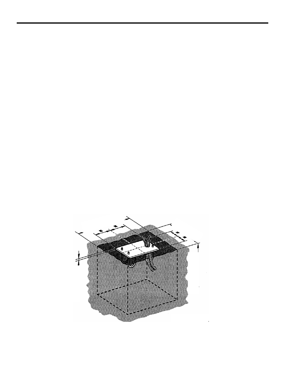
You need to set the concrete forms to provide a cement
footing that is a minimum of 18 by 18 in. (46 by 46 cm)
and that is poured a minimum of 18 in. (46 cm) below
the ground level or just below the frost line, whichever
is greater (see Figure 4). (Your soil conditions will also
affect the size of the cement footing.) To help prevent
rust, the top of your cement footing should be above
ground level.
Within the form boundaries you must locate the
electrical conduit so that it will protrude through the
foundation plate (the plate is provided as an option) and
above the top of the foundation plate about
1/2 in. (1.3 cm).
The exact placement of the conduit is determined partly
by the foundation plate you use and more importantly
by the access holes in the bottom of the operator
cabinet (see Figure 5). If you choose to supply your own
foundation plate, be sure to use steel that is 3/8 in. (1
cm) thick for the plate and be sure to provide a hole
large enough to accommodate your two electrical
conduits, one for high-voltage wire and one for low-
voltage wire. In addition, your foundation plate needs
four 1/2-in. (1-1/4 cm) anchor bolts that extend at least
6-1/2 in. (16-1/2 cm) into the cement footing. The
anchor bolts should be positioned to match the holes in
the bottom of your operator's cabinet.
1/
4”
24”
15”
18
”
After the concrete is poured in the forms and before it
sets, place the foundation plate in the cement so that the
top of the plate is level and flush with the top of the
cement.
Allow the concrete to set a minimum of two full days
before you mount the operator cabinet.
With the key provided, open the operator's panel door
and lift the door away from the cabinet. It may be
necessary on your model of operator to disconnect the
wiring to the fan on the panel door to allow you to more
easily handle the heavy cabinet.
Set the operator cabinet on the foundation plate, aligning
the holes in the bottom of the cabinet with the bolts and
conduit protruding above the foundation plate. Bolt the
cabinet to the foundation plate and cement footing. If
necessary, reconnect the wiring to the fan on the panel
door.
Before connecting the main power to your barrier, you
must remove the vent screw on the hydraulic power pack.
Midway along the top, left edge of the hydraulic power
pack is a 3 mm Allen screw. Remove it now. Failure to
remove the screw can result in erratic operation of the
barrier beam. Do not throw the screw away in case you
ever need to transport the barrier unit or its hydraulic
power pack.
Figure 4. Recommended Concrete Form Dimensions