Controlled Products Systems Group 10463283 User Manual
Page 12
P a g e 1 2
Ja nua ry , 2 00 7
6 2 0 /6 40 O pera tor And
6 2 4B LD C ontr ol Pa ne l Ins tal la tion M a nual
A
DJUST
THE
H
YDRAULIC
P
RESSURES
Now that the beam is attached, re-engage the hydraulic
operation of the barrier by rotating the Manual Release
key clockwise.
Send an opening activating signal to the barrier. The
signal should open the barrier. If it does not open,
increase the pressure of the opening bypass valve (the
green valve) by turning the screw clockwise in small,
1/8- turn increments until the beam does open.
Test the closing of the barrier in the same way. If the
beam fails to move in the closing direction, then
increase the pressure of the closing bypass valve (the
red valve) by turning the screw clockwise in small
increments until the beam does close.
Remember that you should set the bypass pressure
valves so that the beam works with the least pressure
necessary. It is a safety feature of the barrier that the
beam should apply no more than about 33 lb (15 kg)
force against any obstacle it might encounter.
WARNING! For maximum safety to people and
property, use photo eyes and other non-contact
reversing devices in addition to adjusting the
bypass pressure valves to the minimum settings.
I
NSTALLING
THE
E
MERGENCY
B
YPASS
S
OLENOID
AND
ANTI
-
VANDALISM
VALVE
(230V
AC
M
ODELS
O
NLY
)
WARNING! Turn the main power off before you
make any electrical connections or set any
switches inside the control panel box.
The emergency bypass solenoid automatically
disengages the hydraulic system of the barrier beam
when the main power is not available. This allows the
barrier to be raised by hand so that people and vehicles
can safely pass during power interruptions and failures
without having to manual release the barrier.
Note: Once the emergency bypass solenoid has
disengaged the hydraulic system and once you
have raised the beam by hand, you cannot lower
the barrier beam until the power is restored or
by using the manual release key.
If you are installing the optional emergency bypass
solenoid, you must first turn off the main power and
disengage the hydraulic system by using the Manual
Release key.
Then you disassemble the hydraulic lines between the
pistons and the operator so that you can install new
hydraulic pipe fittings.
After installing the new pipe fittings, install the
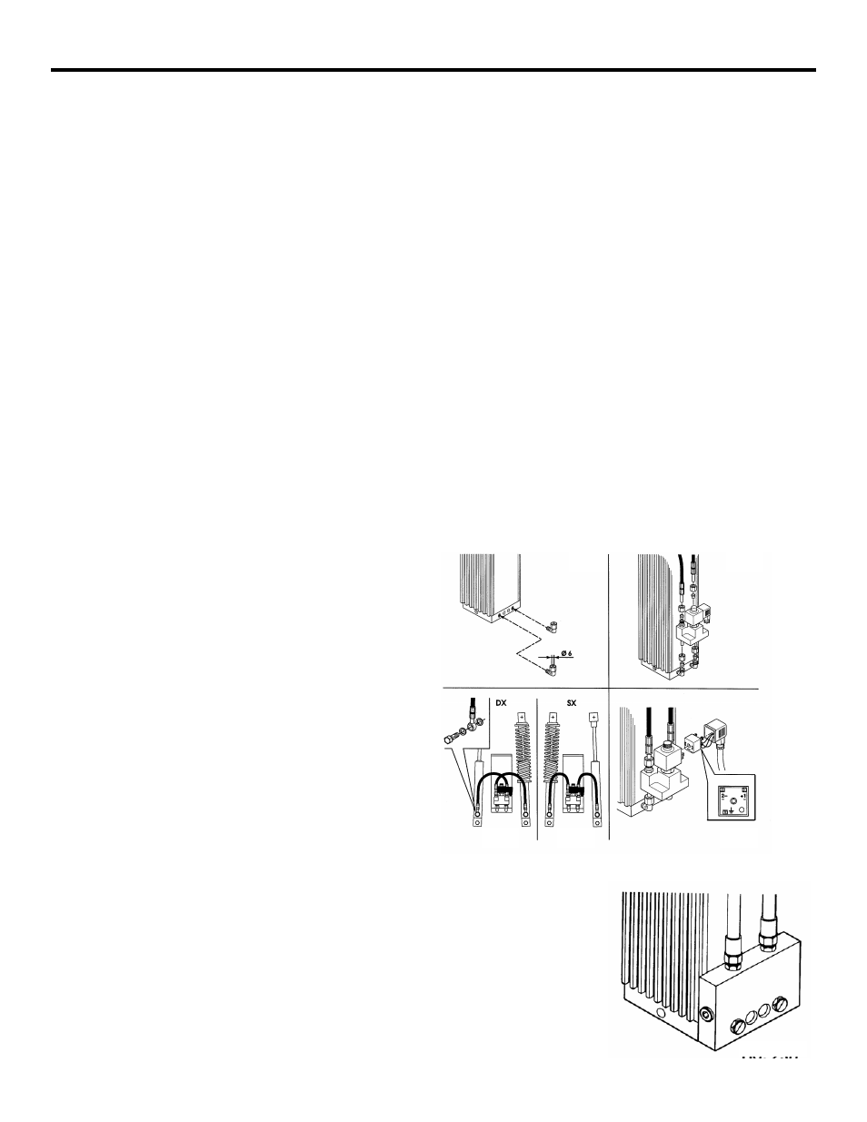
emergency bypass solenoid as shown in figure ()
After connecting the solenoid, you need to connect the
hydraulic lines between the operator and the pistons.
How you connect the lines depends on the orientation
of your barrier installation (see Figure 11).
Finally, connect the solenoid to your main power line
so that it can sense when power is or is not available
(see Figure 11).
Re-engage the hydraulic system with the Manual
Release key so that you can test the installed solenoid.
To test the solenoid, turn off the power to the barrier. If
the solenoid works, you should be able to raise the
beam but not lower it after raising it. You should be
able to lower the beam only after turning the power
back on.
Install the anti-vandalism
valve with the instructions
that are provided with it in
it’s packaging.
Figure 11. Emergency By-Pass Valve
and the Anti-Vandalism Valve