Controlled Products Systems Group 10463283 User Manual
Page 11
P a g e 1 1
Ja nua ry , 2 00 7
6 2 0 /6 40 O pera t or A nd
6 2 4B LD C ontr ol Pa ne l Ins talla tio n M a nual
C
HECK
THE
C
OMPRESSION
S
PRING
The compression spring should be adjusted so that it
holds the beam in any position that it is placed while in
manual mode. (Manual mode is discussed on page 7
shown in Fig. 2)
Move the beam by hand to a half-opened position. The
beam should stay there when you remove your hand.
Note: All compression spring adjustments should
be made with the beam in the vertical (open)
position.
If the beam drifts toward the closed position, turn the
adjuster nut (shown in Fig. 10) clockwise to tighten the
compression spring.
If the beam drifts toward the opened position, turn the
adjuster nut (shown in Fig. 10) counterclockwise to
loosen the compression spring.
.
Note: Proper adjustment of the spring will
counterbalance the beam. This will allow the
minimal pressure setting necessary to move the
beam in a smooth movement.
NOTE: The spanner wrench shown in figure 10
is NOT sold by FAAC or needed top make this
adjustment.
A
TTACH
THE
B
ARRIER
B
EAM
WARNING! Do not install the barrier in such a way
that the beam moves within 2 feet (610 mm) of a
rigid object.
Before you attach the barrier beam, be sure you have
disconnected the barrier from hydraulic operation by
means of the Manual Release mechanism (turning the
key counterclockwise).
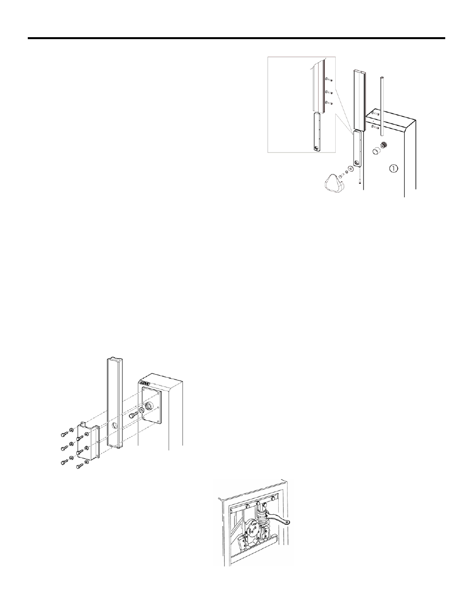
Next you attach the beam to the operator cabinet with
the beam in a vertical position. See Figure 8 if you are
attaching an aluminum beam to a model 620
operator ,see Figure 9 if you are attaching an aluminum
beam to a model 640 operator. (Wooden beams require
additional sandwich plates).
C
HECK
THE
M
ECHANICAL
S
TOPS
First, be sure the hydraulic operation of the beam is still
disengaged (the Manual Release key should be turned
counterclockwise). Next, move the beam by hand from
the fully opened position (vertical) to the fully closed
position (horizontal) and back to the fully opened
position. If the positions are not perfectly vertical and
perfectly horizontal, then adjust the mechanical stops
as necessary (see Figure 7) using a 17mm socket
wrench. The jam nut must be loosened first and
tightened last.
615/620
Figure 8. Beam Attachment 620 (Aluminum Beam)
Figure 9. Beam Attachment 640 (Aluminum Beam)
Figure 10. Adjuster Nut
640