Controlled Products Systems Group 10463283 User Manual
Page 6
P a g e 6
Ja nua ry , 2 00 7
6 2 0 /6 40 O pera t or A nd
6 2 4B L D C o ntr o l Pa ne l Ins tal la t io n M a n ual
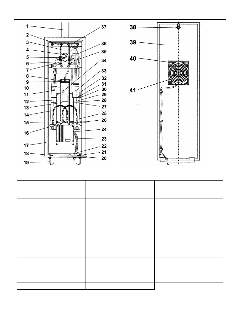
1 Aluminum Beam
15 Pressure Adjusting Screw
29 Right Side Piston
2 Left Hand Stop
16 Pressure Adjusting Screw
30 Spring Support (large spring
groove)
3 Rocker Assembly
17 Cabinet
31 Spring Support Ring
4 Right Hand Limit Adjuster
18 Hole for conduit/wire
32 Spring
5 Left Hand Limit Adjuster
19 Anchor Bolt
33 Right Side Piston Bleed Screw
6 Rocker Arm
20 Foundation Plate (Optional)
34 Thermal (On Older Models)
7 Left Side Limit Switch
21 Hole for conduit/wire
35 Right Side Limit Switch
8 Oil Fill Cap
22 Grounding Lug
36 Spring Adjuster Nut
9 Vent Screw
23 Conduit (Not Supplied)
37 Right Hand Stop
10 Cooling Fins (On motor/pump
24 Control Panel Enclosure
38 Lock
11 Left Side Piston Bleed Screw
25 Hydraulic Hose
39 Door
12 Left side Piston
26 Manual Release
40 Screen For Air Intake
13 Motor Pump Assembly
27 Spring Support (small spring
41 Cooling Fan
14 Hydraulic Hose
28 Screen Cover for Air Intake
Figure 1. The interior of the 620/640 Barrier cabinet (for right-hand orientation)