Nstalling, Arrier – Controlled Products Systems Group 10463283 User Manual
Page 8
P a g e 8
Ja nua ry , 2 00 7
6 2 0 /6 40 O pera tor And
6 2 4B LD C ontr ol Pa ne l Ins tal la tion M a nual
WARNING! Do not install the barrier in such a
way that the beam moves within 2 feet (610
mm) of a rigid object.
Installing the 620 or 640 Barrier System consists of the
following general steps:
•
Determining the orientation of the installation
•
Preparing the forms for the concrete mounting
slab and conduit
•
Mounting the cabinet on the concrete slab
•
Connecting the main power source to the
operator
•
Wiring the control panel for operational logic
•
Wiring additional accessories into the control
panel
•
Decreasing the hydraulic pressures
•
Programming the control panel
•
Attaching the barrier beam
•
Testing the operation of the beam
Note: The following installation instructions
assume you are fully capable of installing an
electronic barrier gate. This manual does not
instruct you in designing a gate, pouring the
cement foundation, or basic electrical wiring. The
installation tasks discussed in this manual are
tasks peculiar to the 620 and 640 Barriers.
D
ETERMINE
THE
O
RIENTATION
OF
THE
I
NSTALLATION
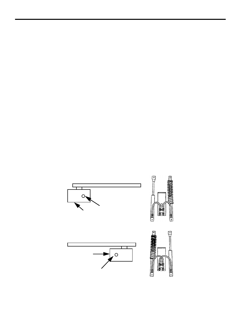
You first need to determine whether your operator is set
up for a right-hand or left-hand installation (see Figure 3).
Open the panel door of the operator cabinet with the key
provided and lift the door up and away from the cabinet,
taking care not to disconnect the cabling to the fan. Look
at the two pistons to see which has the compression
spring surrounding it. Compare your operator with Figure
3 and use the figure to help you determine the orientation
of your installation.
If your operator is not in the correct orientation, turning
the cabinet around 180 deg is the easiest way to solve the
problem. We suggest you call us if your installation site
cannot accommodate this solution since the orientation of
the barrier can be changed with about an hour’s worth of
work.
NOTE: It make no difference if the
hoses are crossed or not.
Beam side
Beam
Cabinet
Panel
side
Compression
spring
Compression
spring
Panel
side
Cabinet
Beam
Beam side
(a) Right-hand orientation: top view and hose connections
(b) Left-hand orientation: top view and hose connections
I
NSTALLING
THE
B
ARRIER
Figure 3. Right Hand vs. Left Hand Installation of the 620/640 Barrier