42 5 d c, Ont r ol, Ane l – Controlled Products Systems Group 104572 User Manual
Page 20: Nstalla t ion, Nstr ucti ons
Pag e 20
Jul y , 2 00 6
3 9 0 24 v O pe ra t or And
4 2 5 D C ontrol Pa ne l I nsta ll a ti on Ma nua l
T
HE
42
5 D
C
ONT
R
OL
P
ANE
L
I
N
STALLA
T
ION
I
NSTR
UCTI
ONS
D
ISPLAY
D
ESCRIPTIONS
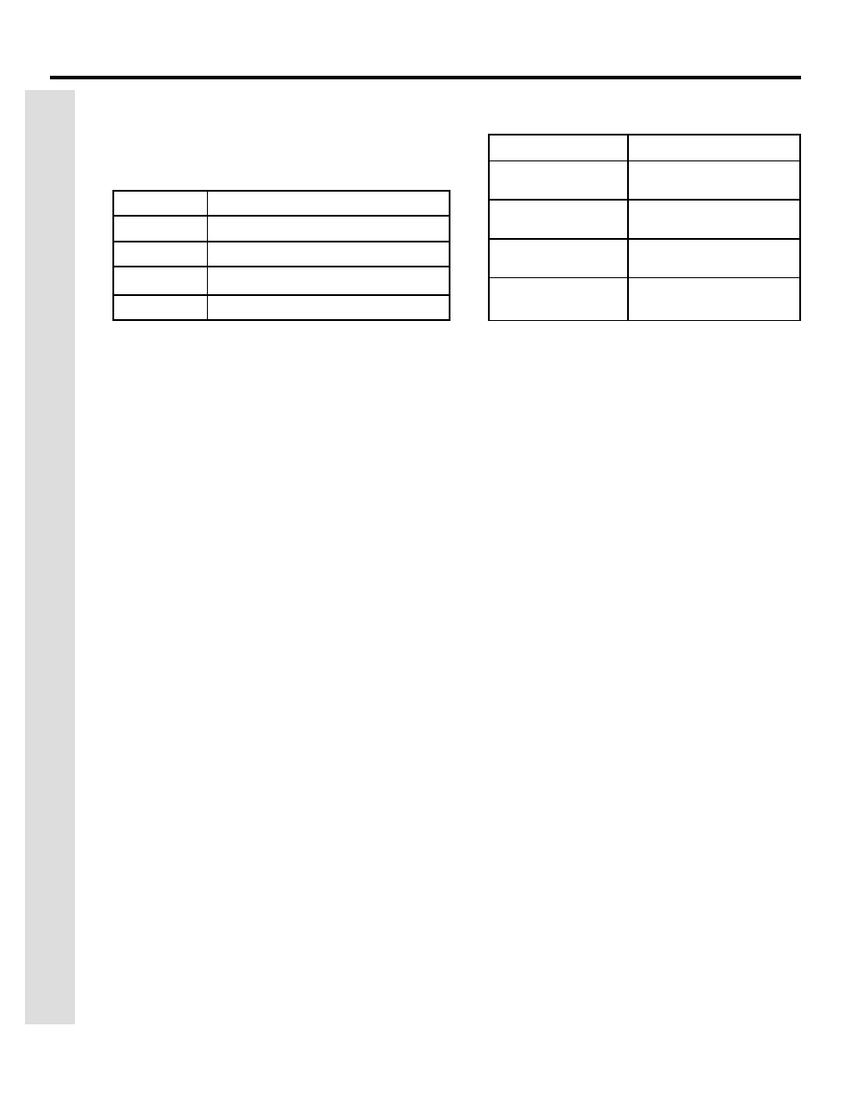
The following table shows the descriptions of the display
during a normal operating procedure
P
ROGRAMMING
THE
MOTOR
RUN
TIME
N
OTE
: The operators will run at slow speed during the motor
run time programming phase.
The 425D features a self learning function for programming
the motor run time, pause time, and deceleration of the 390
24V Operator(s). Follow the procedure below to complete this
function.
1. Manually release the 390 operator(s), move the gate(s) to
the halfway position, and reengage the operator(s). See
figure 3, page 5.
2. Turn the power on. Ensure that the power led (DL1) is on.
3. Press and hold the P2 button until the display shows its
first value. (Example A1,A2,A3, Or A4)
4. Give the panel an open activation with any normally open
device wired to the OPEN A and COM terminals or the
FAAC plug in radio receiver. Motor 2 should close first,
followed by motor 1.
5. If either gate moves toward the open direction, touch the
two RESET (JMP1) pins, (see figure 2) with a small
screwdriver or piece of wire. This will cause the gate to
stop.
6. Turn the power off to the control panel and reverse the
motor wires to the operator that ran open. Turn the
power back on to the control panel and start again at
step 1.
7. Once the motor(s) is (are) running toward the closed
position, it (they) should do so until the closed limit
switch is reached.
8. After 2 seconds, motor 1 should begin to run open, after
and after another 2 seconds motor 2 should run open. It
(they) continue until the open limit switch(s) is (are)
reached.
9. When the gate(s) reach the open position, the control
panel begins to count the pause time. Once the desired
pause time (timer to close) has elapsed, give the panel an
open activation. Motor 2 should begin to close, followed
by motor 1. The gate(s) will run until the closed limit
switch(s) is (are) reached.
10. Programming is now complete. The display will show
“— —”.
Value Shows
Descriptions
—— ——
Gate Closed and at Rest
OP
Gate is Opening (Open in “E” Mode)
tc
Timer to Close (Pause Time)
CL Gate
is
Closing
F
USE
R
ATINGS
Fuse Protects
F1 = 10Amp
250V
Main Power
F2 = 1.6Amp
250V
Accessories/Charging
Circuit
F3 = .800mAmp
250V
Flashing Light
F4 = 3.15Amp
250V
Electric Lock Output