Controlled Products Systems Group 104572 User Manual
Page 11
Page 11
July , 2 00 6
3 9 0 24 v O pe ra t or A nd
4 2 5 D C ontrol Pa ne l I nsta ll a ti on Ma nua l
1
5
3
6
8
2
4
9
7
3
5
1
A
A
B
A
B
C
C
D
A
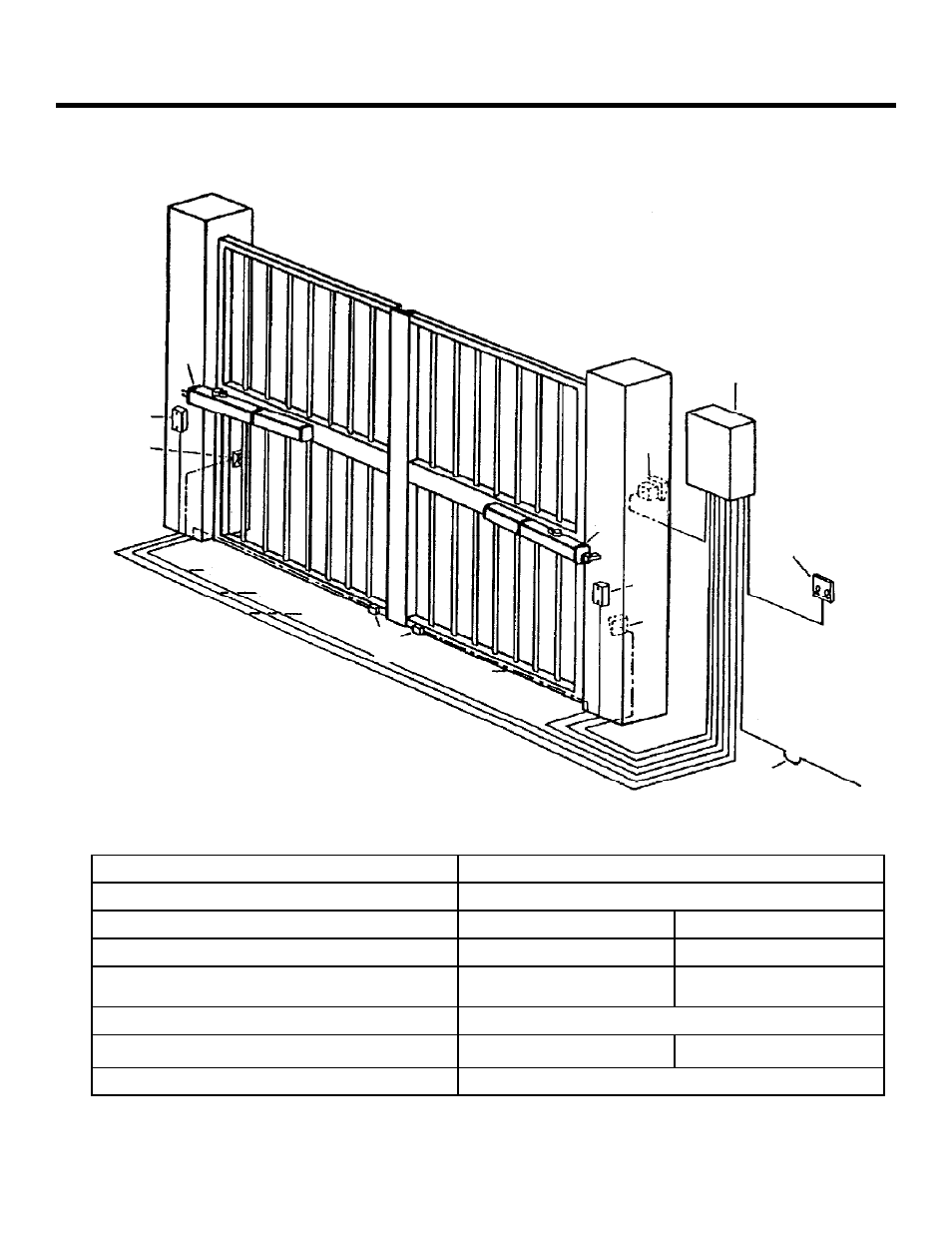
Figure 1. The layout of a sample gate system
NOTE: Locate activation switches at
least10 ft from the gate.
1 Operator
Wire Gauges for Given Voltage
2 Control
Panel/Enclosure
110 VAC primary / 24 VAC 100 VA secondary
3 Photocell
A 2
×
18 AWG
A 2
×
18 AWG
4 Power
Switch
B 4
×
14 AWG
B 4
×
14 AWG
5
FAAC 5 Wire Cable for Master/Slave Connection and
Junction Box
C 5
×
18 AWG
C 5
×
18 AWG
6 Gate
stops
provided by built in limit switch
7
FAAC Key Activated Switch (T10)
A 2
×
18 AWG
A 2
×
18 AWG
8
Wiring to main circuit breaker
D
6
7
8
2
×
12 AWG
See also other documents in the category Controlled Products Systems Group Safety:
- GNC-1 (1 page)
- -108712 (33 pages)
- 1044372 (28 pages)
- 1042071277 (28 pages)
- 104207177 (28 pages)
- 104301 (30 pages)
- 10441811 (29 pages)
- 1044182 (28 pages)
- 1044682 (28 pages)
- 104471 (28 pages)
- 104572 (27 pages)
- 10468583 (36 pages)
- 1049062 (17 pages)
- 106753 (28 pages)
- 108758 (40 pages)
- 109773 (19 pages)
- 10978021 (6 pages)
- 109902 (27 pages)
- 1150-080 (30 pages)
- 1600 (17 pages)
- 1650ETL (23 pages)
- 1650ETL-1K (32 pages)
- 1601-081 (36 pages)
- 1602-091 (42 pages)
- 1602-091 (42 pages)
- 1603-166 (40 pages)
- 1603-166 (38 pages)
- 1603-166 (42 pages)
- 444 XS ST (98 pages)
- 222X383 (84 pages)
- 3020HX (24 pages)
- 3600ETL-1K (36 pages)
- 4500SW (32 pages)
- 6004-080 (34 pages)
- 6002-080 (32 pages)
- 6003-080 (22 pages)
- 6100-083 (56 pages)
- 6100-083 (2 pages)
- 6100-083 (46 pages)
- 6300-087 (59 pages)
- 6300-087 (52 pages)
- 6400-080 (28 pages)
- 6500-087 (48 pages)
- 6500-087 (46 pages)