42 5 d c, Ont r ol, Ane l – Controlled Products Systems Group 104572 User Manual
Page 15: Ns ta ll a t io n, Nstructions
P age 15
July , 2 00 6
3 9 0 24 v O pe ra t or A nd
4 2 5 D C ontrol Pa ne l I nsta ll a ti on Ma nua l
T
HE
42
5 D C
ONT
R
OL
P
ANE
L
I
NS
TA
LL
A
T
IO
N
I
NSTRUCTIONS
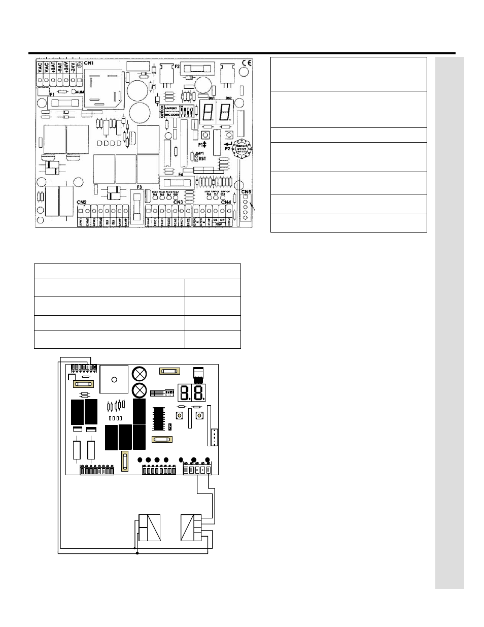
Figure 1. The 425 D Control Panel
CN1 terminal block for main power
supply, battery connections and
accessory power
CN2 terminal block for connecting the
operator(s), lock, and lamp
CN3 limit switch connections
CN4 terminal block for low-voltage
accessories input
CN5 quick connector port for the
FAAC plug in radio receiver.
P1 Programming Push Button
P2 Programming Push Button
Figure 2. The terminal strip wiring of the 425 D with
photobeams
C
ONNECT
O
THER
D
EVICES
WARNING! Turn the main power off before
you make any electrical connections.
P
OWER
S
UPPLY
FOR
A
CCESSORIES
: You can access a
24 VDC output for supplying power to
accessories through terminals +24V and –24V on
terminal block CN1. In most cases, this source
can be used to power 24 VDC accessories.
N
OTE
: The 425 D control panel allows a
maximum accessory load of 630mA.
R
EVERSING
D
EVICES
:
Reversing devices include
photocells, inductive loops, and so forth. All of
the reversing devices should have contacts of the
normally closed (N.C.) type. Where you connect a
device depends on whether you want the device
to operate during opening or during closing.
N
OTE
: UL does not recognize the FAAC
system with loop detectors or safety edges.
FAAC photobeams must be used to comply
with UL 325.
To wire photobeams, refer to page 19 (see FSWOP
for opening photobeams, and FSWCL for closing
photobeams). Photobeams must be connected as
shown. See also page 19 for the wiring of
inductive loops. If using more than one reversing
device, they must be wired in series.
N
OTE
: A shadow/intermittent loop cannot be
wired to for use when using the 425 D
control panel.
F2
F1
RA
DI
O
RESET
F4
F3
FCC1FCA1 FCC2 FCA2
FSW-CL FSW-OP
STOP
P1
P2
-
+
COM
+
-
N.C.
FUSE RATINGS
F1 Main Power
10A
F2 Accessories/Charging Circuit
1.6A
F3 Lamp .800mA
F4 Electric Lock
3.15A