Installing i/o linc, Setting up the i/o linc sensor input – INSTEON I/O Linc (2450) Manual User Manual
Page 5
Page 5 of 16
• Normally Open – When the I/O Linc output relay is open, its Normally Open and Common terminals are
connected
• Common – When the I/O Linc output relay opens and closes, its Common terminal will alternate between
being connected to its Normally Open and Normally Closed terminals
Installing I/O Linc
1)
Plug I/O Linc into an unswitched outlet near your sensor
The white I/O Linc Status LED will turn on
2)
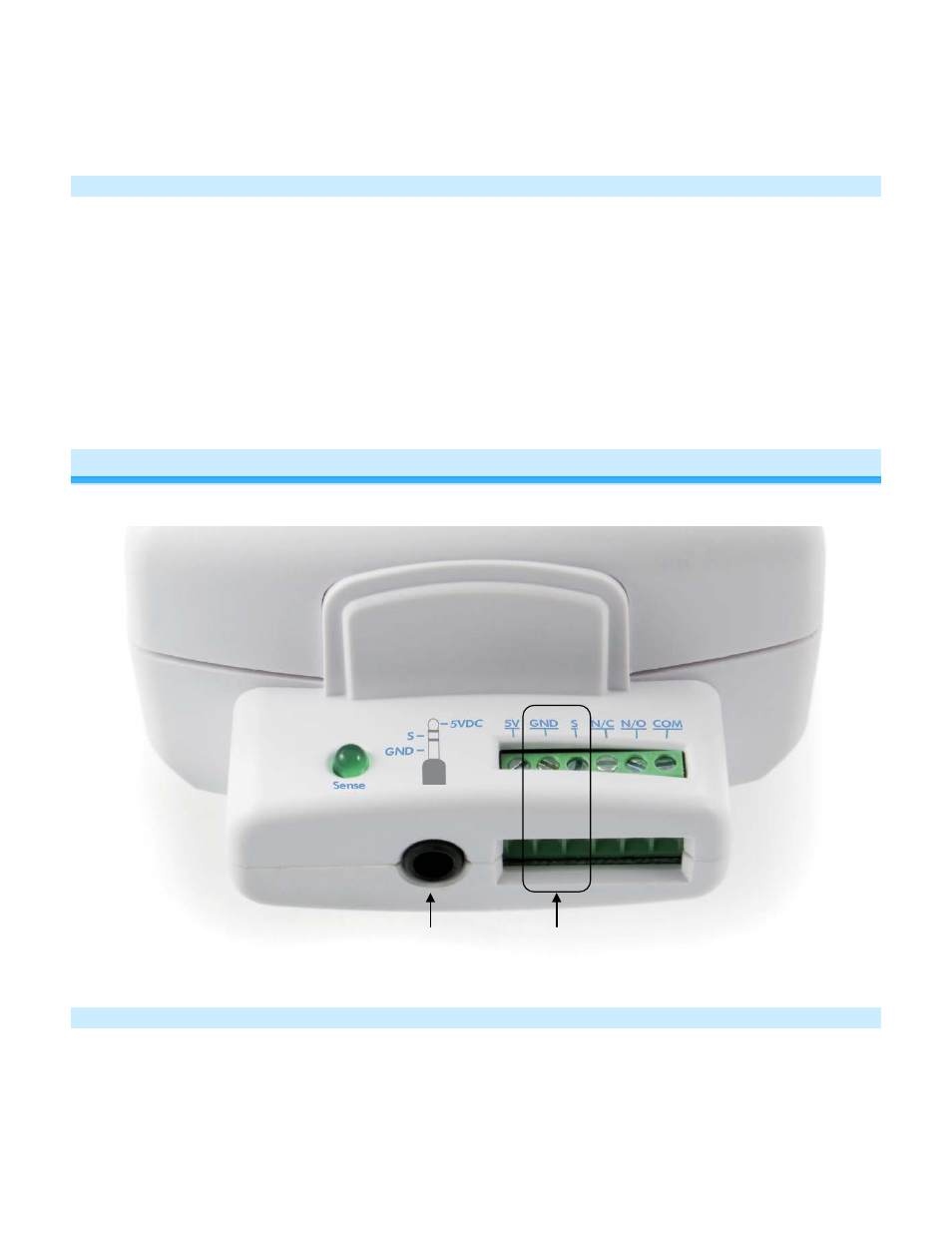
If using a sensor, connect one of its leads to the I/O Linc Ground terminal and the other to the Sense terminal
The green Sensor Status LED will turn on and off when you open and close the sensor
3)
If you are planning to use the I/O Linc output relay, it is recommended to wait until after setting up the I/O Linc
output relay before connecting it. See I/O Linc Output Relay Modes.
Setting Up the I/O Linc Sensor Input
You can connect a sensor to the I/O Linc either using the screw terminals or a sensor that utilizes a 3.5mm connection.
Linking the I/O Linc Sensor Input to an INSTEON Responder
Any device that is Linked to I/O Linc (the load) using these instructions will be controlled when:
•
The I/O Linc connected to the sensor is either opened or closed
•
The I/O Linc Set button is tapped
3.5mm
Sensor
Input
Sensor Screw
Terminals